Table of Contents
- Using Help
- Contacting ASSET InterTech
- Introduction to SourcePoint
- SourcePoint Environment
- SourcePoint Overview
- SourcePoint Parent Window Introduction
- SourcePoint Icon Toolbar
- File Menu
- File Menu - Project Menu Item
- File Menu - Layout Menu Item
- File Menu - Program Menu Item
- File Menu - Macro Menu Item
- File Menu - Print Menu Items
- File Menu - Update Emulator Flash Menu Item
- File Menu - Program Target Device Menu Item
- File Menu - Other Menu Items
- Edit Menu
- View Menu
- Processor Menu
- Options Menu
- Options Menu - Preferences Menu Item
- Options Menu - Target Configuration Menu Item
- Options Menu - Load Target Configuration File Menu Item
- Options Menu - Save Target Configuration File Menu Item
- Options Menu - Emulator Configuration Menu Item
- Options Menu - Emulator Connection Menu Item
- Options Menu - Emulator Reset Menu Item
- Options Menu - Confidence Tests Menu Item
- Window Menu
- Help Menu
- How To -- SourcePoint Environment
- Add Emulator Connections
- Configure Custom Macro Icons
- Configure Autoloading Macros
- Display Text on the Icon Toolbar
- Edit Icon Groups to Customize Your Toolbars
- Modify a Defined Memory Region
- Refresh SourcePoint Windows
- Save a Program
- Start SourcePoint With Command Line Arguments
- Use the New Project Wizard
- Verify Emulator Network Connections
- SourcePoint Overview
- Breakpoints Window
- Breakpoints Window Overview
- How To - Breakpoints
- Code Window
- Command Window
- Command Window Overview
- Confidence Tests Window
- Confidence Tests Window Overview
- Descriptors Tables Window
- Descriptors Tables Window Overview
- How To - Descriptors
- Devices Window
- Devices Window Overview
- How To - Devices Window
- Log Window
- Log Window Overview
- Memory Window
- Memory Window Overview
- How To - Memory Window
- Page Translation Window
- Page Translation Windows Overview
- PCI Devices Window
- PCI Devices Window Overview
- How To - PCI Devices Window
- Registers Window
- Registers Window Overview
- How To - Registers
- Symbols Windows
- Symbols Window Overview
- How To - Symbols Window
- Viewpoint Window
- Viewpoint Window Overview
- Watch Window
- Watch Window Overview
- How To - Watch Window
- Technical Notes
- SourcePoint Command Language
- Overview
- Commands and Control Variables
- aadump
- abort
- abs
- acos
- advanced
- asin
- asm
- asmmode
- atan
- atan2
- autoconfigure
- base
- bell (beep)
- bits
- break
- breakall
- cachememory
- cause
- Character Functions
- clock
- continue
- cos
- cpubreak commands
- cpuid_eax
- cpuid_ebx
- cpuid_ecx
- cpuid_edx
- createprocess
- ctime
- cwd
- dbgbreak commands
- defaultpath
- #define
- define
- definemacro
- deviceconfigure
- devicescan
- disconnect
- displayflag
- do while
- dos
- dport
- drscan
- edit
- editor
- emulatorstate
- encrypt
- error
- eval
- evalprogramsymbol
- execution point ($)
- exit
- exp
- fc
- fclose
- feof
- fgetc
- fgets
- first_jtag_device
- flist
- flush
- fopen
- for
- forward
- fprintf
- fputc
- fputs
- fread
- fseek
- ftell
- fwrite
- getc
- getchar
- getnearestprogramsymbol
- getprogramsymboladdress
- gets
- globalsourcepath
- go
- halt
- help
- homepath
- idcode
- if
- include
- invd
- irscan
- isdebugsymbol
- isem64t
- isprogramsymbol
- isrunning
- issleeping
- issmm
- jtagchain
- jtagconfigure
- jtagdeviceadd
- jtagdeviceclear
- jtagdevices
- jtagscan
- jtagtest
- keys
- last
- last_jtag_device
- left
- license
- linear
- list, nolist
- load
- loadbreakpoints
- loadlayout
- loadproject
- loadtarget
- loadwatches
- log, nolog
- log10
- loge
- logmessage
- macropath
- Memory Access
- messagebox
- mid
- msgclose
- msgdata
- msgdelete
- msgdr
- msgdump
- msgir
- msgopen
- msgreturndatasize
- msgscan
- msr
- num_activeprocessors
- num_all_devices
- num_devices
- num_jtag_chains
- num_jtag_devices
- num_processors
- pause
- physical
- port
- pow
- print cycles
- printf
- proc
- processorcontrol
- processorfamily
- processormode
- processors
- processortype
- projectpath
- putchar
- puts
- rand
- readsetting
- reconnect
- Register Access
- reload
- reloadproject
- remove
- reset
- restart
- return
- right
- runcontroltype
- safemode
- save
- savebreakpoints
- savelayout
- savewatches
- selectdirectory
- selectfile
- shell
- show
- sin
- sizeof
- sleep
- softbreak, softremove, softdisable, softenable
- sprintf
- sqrt
- srand
- step
- stop
- strcat
- strchr
- strcmp
- strcpy
- _strdate
- string [ ] (index into string)
- strlen
- _strlwr
- strncat
- strncmp
- strncpy
- strpos
- strstr
- _strtime
- strtod
- strtol
- strtoul
- _strupr
- swbreak
- switch
- swremove
- tabs
- tan
- tapdatashift
- tapstateset
- targpower
- targstatus
- taskattach
- taskbreak, taskremove, taskdisable, taskenable
- taskend
- taskgetpid
- taskstart
- tck
- time
- #undef
- unload
- unloadproject
- upload
- unlock
- use
- verify
- verifydeviceconfiguration
- verifyjtagconfiguration
- version
- viewpoint
- vpalias
- wait
- wbinvd
- while
- windowrefresh
- wport
- writesetting
- yield
- yieldflag
Options Menu - Target Configuration Menu Item
Select Options|Target Configuration to open the target configuration dialog.
To move directly to a particular tab, click here:
Memory Map Tab
Program Flash Tab
Memory Map Tab
The Memory Map tab allows you to define regions of memory and control how those regions are accessed by SourcePoint.
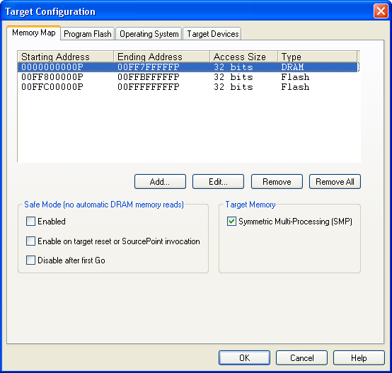
Memory Map tab under Options|Target Configuration
Memory Map text box. The upper half of this tab displays already defined memory map ranges, providing four columns of data labeled Starting Address, Ending Address, Access Size, and Type. These columns are described briefly below:
-
Starting address column. This column lists the physical address where the memory range begins.
-
Ending address column. This column lists the physical address where the memory range ends.
-
Access Size column. This column lists the physical memory width (8, 16, or 32 bits) that is used when memory within this range is read or written to.
-
Type column. This column lists the type of memory: SRAM, DRAM, ROM, or Flash.
Buttons. The four buttons beneath the text box let you add, modify, or delete the data in the Memory Map text box.
-
Add button. Opens an Add Memory Map Entry dialog box for use in adding a memory range.
-
Edit button. Opens an Edit Memory Map Entry dialog box for use in editing a memory range.
-
Remove button. Removes a highlighted memory range.
-
Remove All button. Removes all memory ranges.
For more information on how to create or edit these data, see "How to Modify a Defined Memory Region," part of "How To - SourcePoint Environment," found under SourcePoint Environment.
Safe Mode (no automatic memory reads) section. The options in this section let you determine the parameters for entering Safe Mode.
Note: Normally, SourcePoint automatically refreshes memory-based windows by re-reading target memory after the target stops, steps, or resets. In some targets, however, reading memory immediately following a reset hangs the target processor. For instance, if a Memory window is open and the memory displayed is in an area that is unavailable until the chipset is initialized, then clicking the Reset icon hangs the target. This is also a potential problem with the Code, Memory, Trace, Page Translation, and Devices windows (all windows that can cause target memory reads).
-
Enabled. If the Enabled option is checked, then Safe mode is enabled and automatic refresh of memory-based windows is disabled. When Safe mode is enabled, SourcePoint displays the text ”(Safe mode)” in the SourcePoint title bar.
-
Enable on target reset or SourcePoint invocation. If this option is checked, Safe mode is enabled automatically on target reset or SourcePoint invocation, and automatic refresh of memory reads is disabled.
-
Disable after first Go. This option automatically disables Safe mode following a target run.
If all three check boxes are checked, Safe mode is enabled upon target reset, but it is disabled again when the next Go command is issued by the user. This gives you a convenient way to avoid the hazard of windows that cannot be refreshed safely immediately following a target list.
If Safe mode is in effect for a memory range, and that range currently is displayed in a window, the following occurs:
-
A Code window displays a No data available message.
-
A Memory window displays question marks instead of data.
-
Other memory-based windows display old data.
The Refresh button of a window always forces memory reads to occur for the data range in that window.
Target Memory section. If you are working in a multi-processing setup, a Target Memory section displays to the right of the Safe Mode section. The section contains the option Symmetric Multi-Processing (SMP). A Symmetric Multi-Processing (SMP) system is a multi-processor system in which the memory maps of all processors are identical. In other words, all memory is available to all processors at exactly the same address. Check this box if your target is an SMP system.
If the SMP box is not checked, SourcePoint adds a Processor ID column to the Memory Map text box so that you can declare memory ranges for each processor independently. A memory range may belong to a single processor or all processors. The concept of a range of memory being shared by some processors, but not all processors, is not supported.
In single processor systems, the SMP check box does not display.
Program Flash Tab
The Program Flash feature allows you to program the flash device(s) on a target platform. You must specify a binary file containing the data to be programmed and can also specify a target initialization macro to perform any target initialization that may be required before programming the flash device.
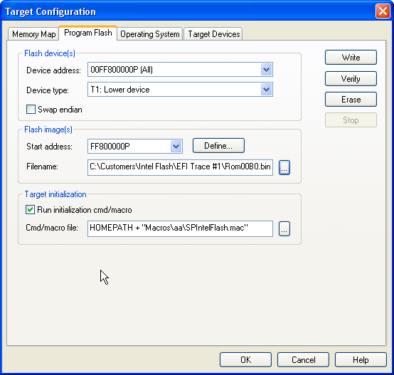
Program Flash tab under Options|Target Configuration
Flash Device(s) Section
Device address. Select the correct device address from the drop down list populated from the memory map.
Device type. The Device type drop down box contains a list of all supported devices. Use the drop down box to select one.
Swap Endian. The purpose of this check box is to allow you to program an image that is backwards in endianness relative to the target. If you have a big endian target and wish to use a little endian image or visa verse, you can enable the Swap endian option. You may want to swap endianness, depending on how your target processor handles byte storage.
Flash Image(s) Section
Start address. If you want to select a previously defined address, use the drop down box to select one. If you want to define a new start address, click the Define button. This opens the Define Flash Image Start Address dialog box. Key in the address there.
Note: The start address is NOT a relative offset. This option allows you to program a specific block/sector within the flash device.
Filename. Enter the flash image file name or click on the Browse button to select a stored file.
Target Initialization Section
Run initialization/cmd macro. Enable this option to run the initialization macro.
Cmd/Macro File. Enter the name of the macro to be executed before a flash operation occurs or click on the Browse button to find it.
Buttons
Write, Verify, Erase, Stop buttons. To execute the macro, click on one of the first three buttons.
The Write button programs the selected flash device.
The Verify button verifies that the selected flash device is programmed correctly.
The Erase button erases the selected flash device.
Use the Stop button to terminate any operation that is currently in process.
Target Devices Tab
This tab displays information about the target JTAG chain.
Target Devices tab under Options|Target Configuration. Note the JTAG chain properties section.
Selecting an item in the tree on the left displays its properties on the right. For the most part, the information is read-only and cannot be modified. However, if SourcePoint does not recognize the JTAG ID of the device, the JTAG properties section includes a Description with a drop-down text box from which you can select a processor type. An IR length and Max JTAG rate spin controls also become editable. Aliases can be added here. If an alias has already been created, it can be edited here.
-
Description. Specifies the target's core/processor.
-
Name. This is SourcePoint's "name" for the processor (P0, P1, P2, etc.).
-
Alias name. Specifies an alias for the device. For instance, P0 could be aliased as BOOT. This alias can then be used throughout SourcePoint where P0 would normally be used.
-
JTAG ID. Specifies the JTAG ID.
-
IR length. Specifies the JTAG instruction register in bits.
-
Max JTAG rate. Indicates the maximum JTAG clock rate.
-
Status. Specifies the status of the device.
Note: Not all controls in the properties section are displayed, depending on the device.