ScanWorks Boundary-Scan Test
About ScanWorks Boundary-Scan Test
ScanWorks Boundary-Scan Test (BST) is optimized for ease and speed of use, high test coverage, long-term reliability and protection of boards under test. Its automated, model-based test development drastically cuts lead times. And the tests you build in one phase can be re-used in the next. It’s a single, unified workflow.
The flexible BST licensing model ensures cost-efficient, agile and strategic deployment of tools throughout your enterprise; in board design prototyping, manufacturing test, and field return repair environments. Deploy just the tools you need in each domain. No surpluses. No slack. Optimum savings.
But what really opens up your future destinations is that ScanWorks BST runs on the ScanWorks Platform, host to a range of other complementary ScanWorks test technologies that can extend board quality control way beyond the capabilities of any boundary scan tester.
A single platform for board validation, test and debug.
- Flexible and cost-efficient, enterprise-wide licensing. Get just the features you need, where you need them, at exactly the right time.
- The unified, platform-based workflow allows tests to be built once and re-used throughout the product life-cycle.
- Automated test development using built-in, constantly expanding device model library dramatically cuts lead times.
- Component models for discrete, non-boundary-scan-enabled devices further increase test development productivity and coverage.
- Parallel testing and programming of up to 128 boards, simultaneously and asynchronously, delivers massive efficiency gains.
- Built-in power safety features prevent board damage on trial testing.
- Multiple reporting formats, including XML, HTML, and Text for easy integration and exact fault location in any environment.
- Excellent project management keeps track of all files and settings for streamlined deployment with any type of hardware.
- Integration in any test executive, including NI LabVIEW and TestStand via the comprehensive BST API compatibility with your existing test methodologies and expertise.
Boundary-Scan Test Development Software
Overview
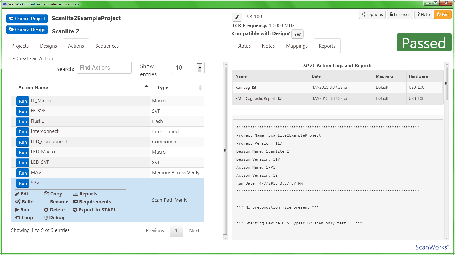
The Boundary-Scan Test (BST) Development Software is one of the several configurations of the ScanWorks boundary-scan (JTAG) test and on-board programming environment. Test engineers can quickly develop interconnect tests and device-programming actions for use on first prototype board to accelerate the board bring-up process. Then tests can be exported for use in manufacturing and repair facilities.
Features
- Extensive, constantly expanding device model library – allows automated test development
- Discrete component models – profiling of even non-boundary-scan devices increases test development automation and test coverage.
- Built-in power safety features – prevent board damage on trial testing.
- Standard XML reporting format – easy integration into other systems.
Boundary-Scan Test Diagnostic & Repair Software
Overview
The ScanWorks BST Diagnostic & Repair Software has been tailored for applications where the fast isolation of faults and the identification of their causes are of paramount importance. Failed printed circuit boards coming off a manufacturing line or faulty product returned by a customer could be routed to the manufacturer’s repair facility. An efficient method for testing circuit boards gives the manufacturer the ability to correct the problem faster and ensure the quality of the assembly. As a result, faulty product can be transformed from a liability into a revenue opportunity much sooner. ScanWorks BST Diagnostic & Repair Software effectively performs circuit board testing and flash memory diagnostics that can save you both time and money in the long run.
Features
- Minimize JTAG test development time by re-using vectors that were created to test prototypes during design or to test boards on a manufacturing line
- Scan individual vectors, run complete actions or run a sequence of actions, all from a simple graphical user interface
- Isolate faults fast with diagnostics that can identify failures down to the pin level or net level
- Diagnose using a debug station that is remote from the manufacturing station that originally failed the test
- View a graphical representation of your PCBA to locate the position of a failing net or device pin
Boundary-Scan Test Manufacturing Software
Overview
With the ScanWorks® Boundary-Scan Test (BST) Manufacturing Software, companies can ensure a higher level of quality for their products because boundary scan gives them test coverage where physical access is not an option. And the return on investment from ScanWorks is very rapid because boundary-scan tests and programming algorithms developed during research and development can be re-used in manufacturing with no alterations.
The ScanWorks BST Manufacturing Software provides a cost-effective means of applying JTAG vectors during high-volume manufacturing. In addition, ScanWorks increases the value of the other testing equipment by sharing the burden of test between those testers and ScanWorks licenses. Compatible with most ICT, MDA, Flying Probe, and Functional Testers, ScanWorks BST Manufacturing Software increases overall test coverage while reducing test costs.
Features
- Increase product quality through higher test coverage brought about by using JTAG (boundary scan) to perform structural test on PCBAs with few test points
- Quickly isolate and diagnose failures
- Re-use JTAG test and programming vectors developed during a product’s design stage
- Easily train new operators on the simple graphical user interface
- Integrate ScanWorks with familiar test executives like LabVIEW®, TestStand, LabWindows/CVI®, and others
- Increase throughput on a manufacturing line by offloading boundary scan test and programming from ICT to ScanWorks
- Reduce ICT fixture costs and improve asset utilization by moving tests from the ICT system to the ScanWorks station
- Increase speed of programming on-board devices through ScanWorks’ high programming clock speeds and parallel multi-board programming capabilities
Dispatcher - Parallel Test and Programming
Overview
Dispatcher for ScanWorks Boundary-Scan Test increases production throughput by cost-effectively applying JTAG vectors during high-volume or high-mix manufacturing.
Dispatcher can test, program or diagnose multiple identical or completely different circuit boards simultaneously. Because it has a .NET-based application programming interface (API), Dispatcher can be readily and easily integrated into your test executive. You’ll be able to connect to local or remote units-under-test (UUT) over an ethernet network or the internet. From your PC’s test executive, you’ll can apply boundary-scan (JTAG) tests or configure programmable devices in-system after they’ve been soldered to a board. Imagine the power of remotely running, evaluating and diagnosing any number of boards based on different designs simultaneously from one test executive.
Features
Dispatcher’s licensing model scales efficiently, ensuring a fast return-on-investment.
- Accelerate throughput on your manufacturing line
- Extremely flexible in high-mix environments
- Very powerful in high-volume environments
- Quickly isolate and diagnose failures on multiple UUTs
- Re-use JTAG test and programming vectors developed during a circuit board’s design stage
- Integrates easily with familiar test executives like LabVIEW®, TestStand, LabWindows/CVI® and others
- Reduce the cost of off-line programming by integrating in-system programming into your assembly line
Boundary-Scan Programming Development Software
Overview
The ScanWorks® Boundary-Scan Programming Development software offers a complete set of tools for in-system programming (ISP) or in-system configuration (ISC). Programming routines can be developed quickly, saving money, time and resources. And the graphical interface on ScanWorks makes the development, debug and execution of programming routines intuitive and easy.
Features
- Model-Based Automated Development of programming operations
- One Environment
- Rapid Test Development
- Powerful Integrated Debuggers
- Excellent Diagnostic and Fault Location
- Easy Integration with ScanWorks APIs
- Accelerated Production Throughput
- Program Multiple Boards in Parallel
- Fully Compatible with Other ScanWorks Products
Chiplet interconnect testing using JTAG/boundary scan
Overview
Since its inception, ScanWorks has provided board-level shorts and opens testing of interconnects between Boundary-Scan devices through use of its Automatic Test Pattern Generation (ATPG) feature.
ScanWorks now generates IEEE 1450 – Standard Test Interface Language (STIL) vectors as a means of describing IEEE 1149.1 and IEEE 1149.6 test patterns and waveforms into a common test language. Once described, these test patterns and waveforms can be ported to another test environment or automatic test equipment (ATE) platforms for application to die-to-die (D2D) interconnects to test for shorts, opens, stuck-at, and bridging faults of D2D interconnections between silicon die of multi-die devices.
Multi-die devices, as products of a heterogenous integration design methodology, are package configurations containing multiple silicon die often referred to as “chiplets”. Chiplets within multi-die devices may vary in function, process technologies, and may be supplied from different die manufacturers.
Features
- Multi-die device suppliers can provide their ScanWorks project used to generate the STIL patterns to downstream board designers and contract manufacturers
- Board designers can apply D2D interconnect tests to the board and to the multi-die device to confirm quality
- Problems found with the multi-die device can be traced back to the package supplier who has the same test on their ATE to help debug whether it is a board or multi-die package issue
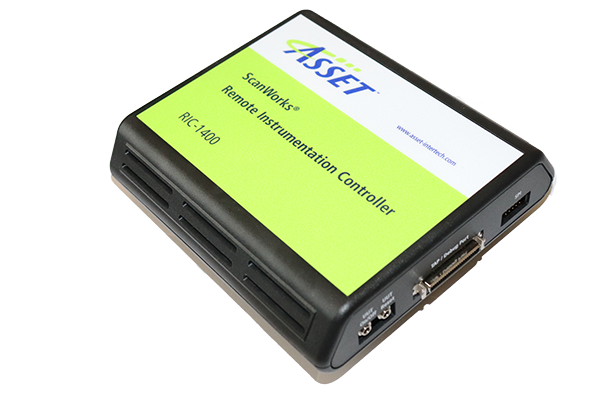
The ScanWorks platform for embedded instruments is supported by a wide variety of hardware controllers and accessories with which engineers can connect ScanWorks to their unit under test (UUT). Hardware is available for development, production and repair environments. The test platform required for ScanWorks is either a standard PC or a system with a built-in (embedded) JTAG controller.
ScanWorks Boundary-Scan Test eResources

The ability to thoroughly test, characterize and diagnose faults and failures with soldered-down memory is one of the most pressing problems in the industry. With ASSET InterTech’s ScanWorks® Boundary-Scan Test, engineers designing with Double Data Rate 4 (DDR4) memory devices can facilitate shorts and opens testing on control, address, and data lines.


Blog Posts About ScanWorks Boundary-Scan Test
Combining ASSET Fast Flash Programming Technology with Customer IP – Part 2: Integrating ScanWorks-Generated Instruments into Customer IP
Unlocking the Power of ScanWorks Fast Flash: Integrating Customer IP into FPGA Configurations – Part 1
Unboxing Boundary-Scan Test: Part 5
It’s JTAG’s 35th Anniversary!
Related Case Studies

Zebra Technologies’ portable printer line had reached the end of the road with in-circuit test (ICT). Faced with a new design that could accommodate only 10 – 15 percent node coverage on an ICT system, Zebra’s manager of manufacturing test engineering, had to come up with a more effective high-volume manufacturing test strategy than ICT could provide.