Table of Contents
- Using Help
- Contacting ASSET InterTech
- Introduction to SourcePoint
- SourcePoint Environment
- SourcePoint Overview
- SourcePoint Parent Window Introduction
- SourcePoint Icon Toolbar
- File Menu
- File Menu - Project Menu Item
- File Menu - Layout Menu Item
- File Menu - Program Menu Item
- File Menu - Macro Menu Item
- File Menu - Print Menu Items
- File Menu - Update Emulator Flash Menu Item
- File Menu - Program Target Device Menu Item
- File Menu - Other Menu Items
- Edit Menu
- View Menu
- Processor Menu
- Options Menu
- Options Menu - Preferences Menu Item
- Options Menu - Target Configuration Menu Item
- Options Menu - Load Target Configuration File Menu Item
- Options Menu - Save Target Configuration File Menu Item
- Options Menu - Emulator Configuration Menu Item
- Options Menu - Emulator Connection Menu Item
- Options Menu - Emulator Reset Menu Item
- Options Menu - Confidence Tests Menu Item
- Window Menu
- Help Menu
- How To -- SourcePoint Environment
- Add Emulator Connections
- Configure Custom Macro Icons
- Configure Autoloading Macros
- Display Text on the Icon Toolbar
- Edit Icon Groups to Customize Your Toolbars
- Modify a Defined Memory Region
- Refresh SourcePoint Windows
- Save a Program
- Start SourcePoint With Command Line Arguments
- Use the New Project Wizard
- Verify Emulator Network Connections
- SourcePoint Overview
- Breakpoints Window
- Breakpoints Window Overview
- How To - Breakpoints
- Code Window
- Command Window
- Command Window Overview
- Confidence Tests Window
- Confidence Tests Window Overview
- Descriptors Tables Window
- Descriptors Tables Window Overview
- How To - Descriptors
- Devices Window
- Devices Window Overview
- How To - Devices Window
- Log Window
- Log Window Overview
- Memory Window
- Memory Window Overview
- How To - Memory Window
- Page Translation Window
- Page Translation Windows Overview
- PCI Devices Window
- PCI Devices Window Overview
- How To - PCI Devices Window
- Registers Window
- Registers Window Overview
- How To - Registers
- Symbols Windows
- Symbols Window Overview
- How To - Symbols Window
- Viewpoint Window
- Viewpoint Window Overview
- Watch Window
- Watch Window Overview
- How To - Watch Window
- Technical Notes
- SourcePoint Command Language
- Overview
- Commands and Control Variables
- aadump
- abort
- abs
- acos
- advanced
- asin
- asm
- asmmode
- atan
- atan2
- autoconfigure
- base
- bell (beep)
- bits
- break
- breakall
- cachememory
- cause
- Character Functions
- clock
- continue
- cos
- cpubreak commands
- cpuid_eax
- cpuid_ebx
- cpuid_ecx
- cpuid_edx
- createprocess
- ctime
- cwd
- dbgbreak commands
- defaultpath
- #define
- define
- definemacro
- deviceconfigure
- devicescan
- disconnect
- displayflag
- do while
- dos
- dport
- drscan
- edit
- editor
- emulatorstate
- encrypt
- error
- eval
- evalprogramsymbol
- execution point ($)
- exit
- exp
- fc
- fclose
- feof
- fgetc
- fgets
- first_jtag_device
- flist
- flush
- fopen
- for
- forward
- fprintf
- fputc
- fputs
- fread
- fseek
- ftell
- fwrite
- getc
- getchar
- getnearestprogramsymbol
- getprogramsymboladdress
- gets
- globalsourcepath
- go
- halt
- help
- homepath
- idcode
- if
- include
- invd
- irscan
- isdebugsymbol
- isem64t
- isprogramsymbol
- isrunning
- issleeping
- issmm
- jtagchain
- jtagconfigure
- jtagdeviceadd
- jtagdeviceclear
- jtagdevices
- jtagscan
- jtagtest
- keys
- last
- last_jtag_device
- left
- license
- linear
- list, nolist
- load
- loadbreakpoints
- loadlayout
- loadproject
- loadtarget
- loadwatches
- log, nolog
- log10
- loge
- logmessage
- macropath
- Memory Access
- messagebox
- mid
- msgclose
- msgdata
- msgdelete
- msgdr
- msgdump
- msgir
- msgopen
- msgreturndatasize
- msgscan
- msr
- num_activeprocessors
- num_all_devices
- num_devices
- num_jtag_chains
- num_jtag_devices
- num_processors
- pause
- physical
- port
- pow
- print cycles
- printf
- proc
- processorcontrol
- processorfamily
- processormode
- processors
- processortype
- projectpath
- putchar
- puts
- rand
- readsetting
- reconnect
- Register Access
- reload
- reloadproject
- remove
- reset
- restart
- return
- right
- runcontroltype
- safemode
- save
- savebreakpoints
- savelayout
- savewatches
- selectdirectory
- selectfile
- shell
- show
- sin
- sizeof
- sleep
- softbreak, softremove, softdisable, softenable
- sprintf
- sqrt
- srand
- step
- stop
- strcat
- strchr
- strcmp
- strcpy
- _strdate
- string [ ] (index into string)
- strlen
- _strlwr
- strncat
- strncmp
- strncpy
- strpos
- strstr
- _strtime
- strtod
- strtol
- strtoul
- _strupr
- swbreak
- switch
- swremove
- tabs
- tan
- tapdatashift
- tapstateset
- targpower
- targstatus
- taskattach
- taskbreak, taskremove, taskdisable, taskenable
- taskend
- taskgetpid
- taskstart
- tck
- time
- #undef
- unload
- unloadproject
- upload
- unlock
- use
- verify
- verifydeviceconfiguration
- verifyjtagconfiguration
- version
- viewpoint
- vpalias
- wait
- wbinvd
- while
- windowrefresh
- wport
- writesetting
- yield
- yieldflag
Options Menu - Emulator Configuration Menu Item
The initial host/emulator/target setup is managed by the emulator. Certain defaults are pre-set for optimum communications with the target. You may find, however, that these settings may not be optimum for your setup. One of the ways to make changes is through the Emulator Configuration menu item, which allows you to change certain signaling parameters. Once SourcePoint is running, you can access this menu item and make your changes; after the emulator is reset, it remembers the changes and use them as defaults.
Select Options|Emulator Configuration on the menu bar. One of two Emulator Configuration dialog boxes displays, depending on the attached emulator.
If you are configuring an emulator that supports an ethernet connection, an Emulator Configuration dialog box displaying several tabs appears.
Note: All dialog boxes include a Description field at the bottom. If no particular field is selected in a dialog box, the Description field gives you a brief description of the dialog box itself. If a particular field is selected, the Description field gives you a brief description of that field.
General Tab
The General tab lets you delay target acquisition or disable breakpoints while stepping.
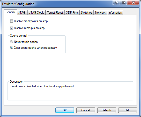
General tab under Options|Emulator Configuration
Disable breakpoints on step. When this option is enabled, breakpoints are disabled when low level stepping is performed. The option is designed to prevent breakpoints in SMM or interrupt code from halting the processor during a single step.
Disable interrupts on step. When this option is enabled, interrupts are disabled when low level stepping is performed. The option is designed to prevent pending interrupt handlers from executing during a single step.
JTAG Tab
The JTAG tab lets you change preset options associated with the JTAG scan chain.
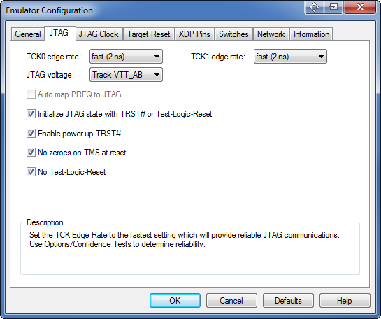
JTAG Tab dialog box
TCK0 edge rate. This option sets the TCK edge rate for the first JTAG chain. Set the TCK edge rate to the fastest setting which will provide reliable JTAG communications. Use Options/Confidence Tests to determine reliability. The choices are: slow (10ns), medium (5 ns), fast (2 ns). The default setting is fast
TCK1 edge rate. This option sets the TCK edge rate for the second JTAG chain. Set the TCK edge rate to the fastest setting which will provide reliable JTAG communications. Use Options/Confidence Tests to determine reliability. The choices are: slow (10ns), medium (5 ns), fast (2 ns). The default setting is fast.
JTAG voltage. Set to the voltage that the pull-ups on the processor(s) TDI and TDO are connected to on target. If that voltage is also connected to pin 43 of the XDP connector, you may choose 'Track VTT_AB'. If in doubt about a suitable level, use 1.2 V. The choices are: Track VTT_AB, 0.9V, 1.0V, 1.1V, 1.2V, 1.3V, 1.4V and 1.5V. The default is 1.2V.
Auto map PREQ to JTAG. This option applies to PBD-S2x personality modules only. When enabled, the emulator automatically determines how PREQ and PRDY pairs are associated with the JTAG order. (JTAG order = Viewpoint.) If not enabled, the emulator assumes PREQ and PRDY Pair 0 is associated with Viewpoint 0, Pair 1 with Viewpoint 1, and so on.
Initialize JTAG state with TRST# or Test-Logic-Reset. This causes the emulator to assert TRST on setup to ensure the target's JTAG chain is initialized. This may cause certain targets to execute a few instructions from reset (including the Intel® Pentium® 4 and Xeon™ processors).
Enable power up TRST#. This option causes the target to be transitioned from TLR state to RTI state as soon as possible after power up. This may be useful in preventing execution of a few instructions from reset.
No zeroes on TMS at reset. This option determines whether zeroes are pumped out on TMS at reset.
No Test-Logic-Reset. Do not drive target through Test-Logic-Reset state during operation.
Caution: For S2Vs, set the strength to 4 or greater if the target without 39 Ohm termination resisters on TCK and TMS. Otherwise, then set the strength to 3 or less.
JTAG Clock Tab
The options on the JTAG Clock tab let you modify JTAG clock settings.
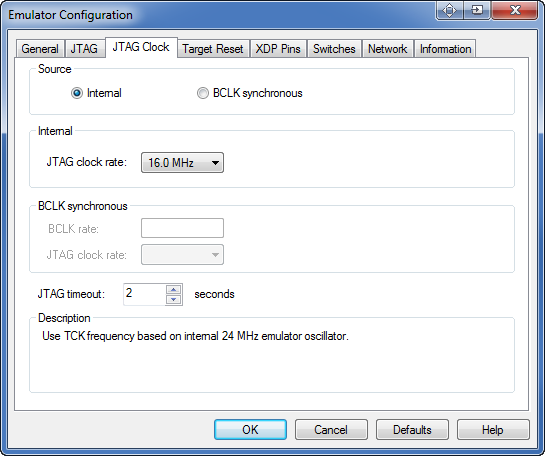
JTAG Clock Tab dialog box
Source field: Internal source. When enabled, this button tells the emulator to derive the TCK rate from its 24 MHz clock source.
Source field: BCLK synchronous. When enabled, this button tells the emulator to derive the TCK rate from the target BCLK signal (BCLK divided by 4 or 8, depending on the type of processor).
Note: BCLK synchronous TCK should not be used with emulators using PBD-S2x personality modules. Click on the Internal source button and use a jumper on the personality module to select BCLK synchronous TCK if desired.
Internal field: JTAG clock rate. This field allows you to specify a clock rate from among the choices provided in the text drop down box.
BCLK synchronous field: BCLK rate/JTAG clock rate. This field allows you to specify a BCLK rate and JTAG clock rate from among choices provided in attendant text drop down boxes.
JTAG timeout. Specifies how long the emulator waits for a response from the target when shifting commands or data on the JTAG chain.
Target Reset Tab
As the name indicates, the options on the Target Reset tab deal with target reset. The options you choose on this tab affect the way the Reset button works on the SourcePoint icon toolbar.
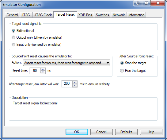
Target Reset Tab dialog box
Note: The options you select below should be determined by the way your target handles reset. For example, some targets may require that you manually toggle a switch to reset it while others reset when a debugger pulls on them. How this works for your target is based on how it was designed to behave. You need to understand that behavior to make appropriate use of this tab.
Target reset signal is section. The options in this section let you select a target operation mode.
-
Target reset is Bidirectional, where the emulator can assert and sense reset
-
Target reset is Output only (driven by emulator), where the emulator can assert reset, but does not sense reset
-
Target reset is Input only (sensed by emulator, where the emulator can sense reset, but not assert reset.
SourcePoint reset causes the emulator to section.
-
Action. There are four options: Wait on manual (external) target reset, Assert reset until target responds, Assert reset for xx ms, then wait for target to respond, or Assert reset for xx ms, don't wait for target to respond.
-
Reset time. Allows you to choose the length of time you want the emulator to wait. (Some targets need longer pulses than others.)
After SourcePoint reset section. There are two options in this section: Stop the target and Run the target.
After target reset, emulator will wait xx ms to ensure stability. Allows you to set a time, in milliseconds, for the emulator to wait after the deassertion of target reset before JTAG communication is attempted.
XDP Pins Tab
This tab displays when you are connected to an ECM-XDP3e emulator.
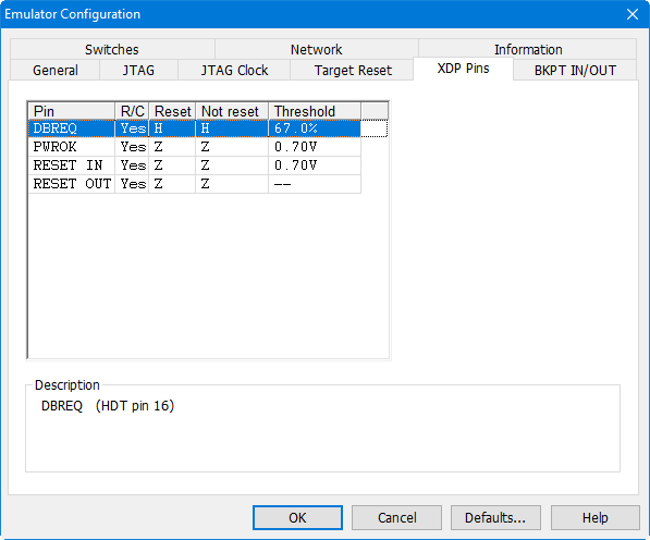
XDP Pins dialog box
These advanced settings control the hardware-level connection to the target. The target configuration file for a specific target will select the correct settings for this tab.
The columns in the pins control identifies each pin’s name and allows low level setup. See the Description field for more details.
Switches Tab
You should use this tab under the direction of Arium technical support personnel.
Network Tab
The Network tab provides a GUI for changing the emulator network settings. This only changes the network settings; it does not affect the entries in the Emulator Connections dialog box.
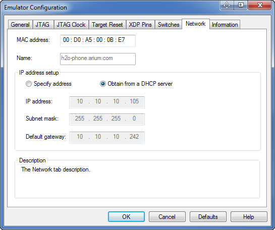
Network dialog box
MAC address and Name. These text boxes identify the emulator on the network. The Name text box may be blank.
IP address setup section
-
Specify address. If you want to use a fixed IP address, you need to select this button and fill in the IP address, Subnet mask, and Default gateway fields in this section. Contact your network administrator if you are unsure what information to use in these fields.
-
Obtain from a DHCP server. Enabling this button automatically fills in the IP address, assuming you have a DHCP server.
Note: Arium recommends you check with your Network Administrator before enabling this option.
-
IP address, Subnet mask, Default gateway. These are the network settings of the emulator.
Note: You can change these settings via this tab. You must reset the emulator for changes to take effect. The changes made here do not modify the emulator connection; you should update that to match. For more information on using the Emulator Connections dialog box, see, "Options Menu - Emulator Connections Menu Item," part of "SourcePoint Overview," found under SourcePoint Environment.
Information Tab
The Information tab gives you information on the configured system you are running currently. The fields are read only and are usually used if you are having problems getting the emulator to work.
Type. This field gives you the name of the emulator to which you are attached.
Firmware. This field displays the revision level (vn.nn) for the two portions of emulator flash memory: boot and flash. Boot memory is the factory programmable portion of flash memory. Flash memory is the field programmable portion.
PBD. This field provides information on the type and revision number of the personality module (JTAG).
Board. This field provides information on the board inside the emulator.
Serial Number. This field gives you the serial number of your emulator.
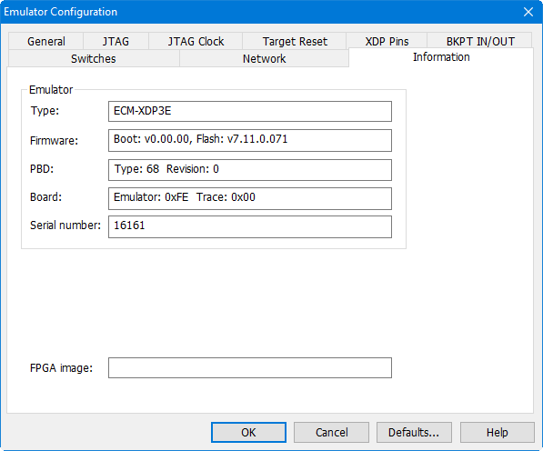
Information Dialog Box