Table of Contents
- Using Help
- Contacting ASSET InterTech
- Introduction to SourcePoint
- SourcePoint Environment
- SourcePoint Overview
- SourcePoint Parent Window Introduction
- SourcePoint Icon Toolbar
- File Menu
- File Menu - Project Menu Item
- File Menu - Layout Menu Item
- File Menu - Program Menu Item
- File Menu - Macro Menu Item
- File Menu - Print Menu Items
- File Menu - Update Emulator Flash Menu Item
- File Menu - Program Target Device Menu Item
- File Menu - Other Menu Items
- Edit Menu
- View Menu
- Processor Menu
- Options Menu
- Options Menu - Preferences Menu Item
- Options Menu - Target Configuration Menu Item
- Options Menu - Load Target Configuration File Menu Item
- Options Menu - Save Target Configuration File Menu Item
- Options Menu - Emulator Configuration Menu Item
- Options Menu - Emulator Connection Menu Item
- Options Menu - Emulator Reset Menu Item
- Options Menu - Confidence Tests Menu Item
- Window Menu
- Help Menu
- How To -- SourcePoint Environment
- Add Emulator Connections
- Configure Custom Macro Icons
- Configure Autoloading Macros
- Display Text on the Icon Toolbar
- Edit Icon Groups to Customize Your Toolbars
- Modify a Defined Memory Region
- Refresh SourcePoint Windows
- Save a Program
- Start SourcePoint With Command Line Arguments
- Use the New Project Wizard
- Verify Emulator Network Connections
- SourcePoint Overview
- Breakpoints Window
- Breakpoints Window Overview
- How To - Breakpoints
- Code Window
- Command Window
- Command Window Overview
- Confidence Tests Window
- Confidence Tests Window Overview
- Descriptors Tables Window
- Descriptors Tables Window Overview
- How To - Descriptors
- Devices Window
- Devices Window Overview
- How To - Devices Window
- Log Window
- Log Window Overview
- Memory Window
- Memory Window Overview
- How To - Memory Window
- Page Translation Window
- Page Translation Windows Overview
- PCI Devices Window
- PCI Devices Window Overview
- How To - PCI Devices Window
- Registers Window
- Registers Window Overview
- How To - Registers
- Symbols Windows
- Symbols Window Overview
- How To - Symbols Window
- Viewpoint Window
- Viewpoint Window Overview
- Watch Window
- Watch Window Overview
- How To - Watch Window
- Technical Notes
- SourcePoint Command Language
- Overview
- Commands and Control Variables
- aadump
- abort
- abs
- acos
- advanced
- asin
- asm
- asmmode
- atan
- atan2
- autoconfigure
- base
- bell (beep)
- bits
- break
- breakall
- cachememory
- cause
- Character Functions
- clock
- continue
- cos
- cpubreak commands
- cpuid_eax
- cpuid_ebx
- cpuid_ecx
- cpuid_edx
- createprocess
- ctime
- cwd
- dbgbreak commands
- defaultpath
- #define
- define
- definemacro
- deviceconfigure
- devicescan
- disconnect
- displayflag
- do while
- dos
- dport
- drscan
- edit
- editor
- emulatorstate
- encrypt
- error
- eval
- evalprogramsymbol
- execution point ($)
- exit
- exp
- fc
- fclose
- feof
- fgetc
- fgets
- first_jtag_device
- flist
- flush
- fopen
- for
- forward
- fprintf
- fputc
- fputs
- fread
- fseek
- ftell
- fwrite
- getc
- getchar
- getnearestprogramsymbol
- getprogramsymboladdress
- gets
- globalsourcepath
- go
- halt
- help
- homepath
- idcode
- if
- include
- invd
- irscan
- isdebugsymbol
- isem64t
- isprogramsymbol
- isrunning
- issleeping
- issmm
- jtagchain
- jtagconfigure
- jtagdeviceadd
- jtagdeviceclear
- jtagdevices
- jtagscan
- jtagtest
- keys
- last
- last_jtag_device
- left
- license
- linear
- list, nolist
- load
- loadbreakpoints
- loadlayout
- loadproject
- loadtarget
- loadwatches
- log, nolog
- log10
- loge
- logmessage
- macropath
- Memory Access
- messagebox
- mid
- msgclose
- msgdata
- msgdelete
- msgdr
- msgdump
- msgir
- msgopen
- msgreturndatasize
- msgscan
- msr
- num_activeprocessors
- num_all_devices
- num_devices
- num_jtag_chains
- num_jtag_devices
- num_processors
- pause
- physical
- port
- pow
- print cycles
- printf
- proc
- processorcontrol
- processorfamily
- processormode
- processors
- processortype
- projectpath
- putchar
- puts
- rand
- readsetting
- reconnect
- Register Access
- reload
- reloadproject
- remove
- reset
- restart
- return
- right
- runcontroltype
- safemode
- save
- savebreakpoints
- savelayout
- savewatches
- selectdirectory
- selectfile
- shell
- show
- sin
- sizeof
- sleep
- softbreak, softremove, softdisable, softenable
- sprintf
- sqrt
- srand
- step
- stop
- strcat
- strchr
- strcmp
- strcpy
- _strdate
- string [ ] (index into string)
- strlen
- _strlwr
- strncat
- strncmp
- strncpy
- strpos
- strstr
- _strtime
- strtod
- strtol
- strtoul
- _strupr
- swbreak
- switch
- swremove
- tabs
- tan
- tapdatashift
- tapstateset
- targpower
- targstatus
- taskattach
- taskbreak, taskremove, taskdisable, taskenable
- taskend
- taskgetpid
- taskstart
- tck
- time
- #undef
- unload
- unloadproject
- upload
- unlock
- use
- verify
- verifydeviceconfiguration
- verifyjtagconfiguration
- version
- viewpoint
- vpalias
- wait
- wbinvd
- while
- windowrefresh
- wport
- writesetting
- yield
- yieldflag
Devices Window Introduction
To open the Devices window, select View|Devices or click on the Devices icon on the toolbar. If it is your first time opening the Devices window, you are prompted to select a device file.
The left-hand pane of the Devices window is called the Devices pane. This is a simple tree structure of devices. The right-hand pane is referred to as the Grid pane. Once you have selected a device from the Devices pane, the corresponding predefined cells are displayed in the Grid pane.
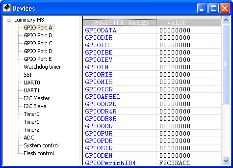
Devices window
Device View Files - Overview
The Devices window allows you to define a custom view of memory. A common use of this view is to display the memory mapped I/O of the devices within a system. The format of this view is defined by one or more text files called device view files. The extension for these files is ”dev”. Each file contains definitions for one or more devices. Each device contains a number of cell definitions.
Arium provides device view files for many common processors. These are located in Targets\Device_view under the directory where SourcePoint was installed. For other processors, a text editor can be used to create your own device view files. The Arium-provided files provide examples of how to create these files.
Device View File Structure
Device view files are simple text files. White space is ignored. Keywords are case-insensitive. Standard C++ comments (//) are allowed.
Each Device view file contains one or more device definitions. The syntax for a device definition is as follows:
[Device#]
<device directives>
<enumerations>
<cell definitions>
The Device# entry specifies the device number. Device numbering begins with 0 and must be numbered consecutively in the file.
Cell Definitions
The general syntax for a cell definition is as follows:
Cell#=<row#>,<column#>,cell-type,options
where:
cell-type = {TEXT | REG | MSR | MEM | IO | SIO | USER | CHILD}
Row and column numbers are 0-based.
Text cells. Text cells allow you to display a label in a cell.
Syntax:
CELL#=<row#>,<column#>,TEXT,<text enclosed in quotes>
Example:
CELL0=1,1,TEXT,”Hello world!”
The above example creates a text cell in the second column of the second row and inserts the phrase ”Hello world!” into it. The maximum text length is 100 characters.
Memory cells. Memory cells allow you to display and change the contents of a memory location. The memory location is limited to lengths of 1, 2, 4, or 8 bytes.
Syntax:
CELL#=<row#>,<column#>,MEM,<address>,<length in bytes>
Example:
CELL0=0,0,MEM,1000p,1
The above example creates a memory cell in the first column of the first row and displays 1 byte of memory starting at physical address 1000.
Note: When SourcePoint reads memory, it reads 128 byte blocks to speed up display. On some systems this may be a problem (e.g., reading the area between memory-mapped I/O). If this is the case, create a memory map entry encompassing the memory cells (Options|Target Configuration) and set the type to I/O. This forces SourcePoint to read each cell separately, and only read the exact number of bytes defined in the cell.
Register cells. The Devices window is not limited to displaying memory. Register cells allow you to display and change the contents of a register.
Syntax:
CELL#=<row#>,<column#>,REG,<register name>
Example:
CELL0=0,1,REG,EIP
The above example creates a register cell in the second column of the first row and displays the value of the EIP register in the cell.
MSR cells. MSR cells allow you to display and change the contents of an MSR.
Syntax:
CELL#=<row#>,<column#>,MSR,<MSR address>
Example:
CELL0=0,1,MSR,80
The above example creates an MSR cell in the first column of the first row and displays the value read from MSR 80H. The MSR value is re-read every time the target stops.
I/O cells. I/O cells allow you to display and change the contents of an I/O port.
Syntax:
CELL#=<row#>,<column#>,IO,<port address>,<port size>
Example:
CELL0=0,0,IO, 80, 1
The above example creates an I/O cell in the first column of the first row and displays an 8-bit value read from I/O port 80H. The port value is re-read every time the target stops.
Indirect I/O cells (IA-32 processors only). Indirect I/O cells allow you to display and change the contents of an indirect I/O location.
When reading or writing a data value, the index value is first written to the port specified by the IndexPort directive. The data value is then either written to, or read from, the port specified by the DataPort directive.
Syntax:
CELL#=<row#>,<column#>,SIO,<index>
Note: An error is generated if an indirect I/O cell is defined with missing IndexPort or DataPort directives.
Example:
IndexPort=70h,1
DataPort=71h,1
CELL0=0,0,SIO, 30h
The above example creates an indirect I/O cell in the first column of the first row and displays an 8-bit value read from index 30 of indirect I/O port pair 70/71. The value is re-read every time the target stops, or when refresh is selected from the context menu.
User-defined cells. User-defined cells allow you to enter an expression to be evaluated every time the target stops. Any expression that can be evaluated in the Command window can be specified. User-defined cells are read-only.
Syntax:
CELL#=<row#>,<column#>,USER,expression
Example:
CELL0=0,0,USER, li + uli
The above example creates a user-defined cell in the first column of the first row and displays the sum of program symbols li and uli. The expression is re-evaluated every time the target stops.
Child cells. Child cells display a portion of another register or memory cell (within the same device) and extract a variable number of bits at a particular offset.
Syntax:
CELL#=<row#>,<column#>,CHILD,<parent row>,<parent column>,<offset>,<length>, <name>.
Example:
CELL0=0,1,REG,CPSR
CELL1=5,1,CHILD,0,1,5,1,T
The above example creates two cells. First it creates a register cell and places the value of CPSR into that cell. The second cell’s definition creates a child of the first cell, displaying Bit 5 of CPSR (the T bit).
Child values are automatically shown in the tooltip help of parent cells. They are also shown when the parent cell is expanded. See below for more information. If you specify a negative row or column number for a child cell, then a cell will not be created. This is useful when the only place you want to see the child value is in the tooltip of the parent.
Directives
Name directive. Specifies the name for a device (the name that appears in the Devices pane). This directive is required.
Syntax:
Name = <name>
Example:
[Device0]
Name = Uart
Base directive. Specifies a base address for all memory cells within a device definition. Once defined, memory cells can specify addresses relative to this base address. See the RepeatDevice directive below for an example of where this might be useful.
Syntax:
Base = <address>
Example:
[Device0]
Name = Uart
Base = 3FFF0000
Cell0 = 0, 0, MEM, base+1CF8, 4
In this example a memory cell is defined at address 3FFF1C8 (3FFF000 + 1CF8).
Processor Directive. In a multi-processor target, specifies which processor to use when reading memory and registers. Processors can be specified numerically (e.g., 0, 1, 2, 3), alpha-numerically (e.g., P0, P1, P2, P3), or alpha only (e.g., AHB, APB). If this directive is not specified, then the current viewpoint processor active when the Device view file is loaded is used.
Syntax:
Processor = #
Example:
[Device0]
Name = Uart
Processor = 1
RepeatDevice directive. This directive allows creation of a device that has a definition identical to a previously defined device. This is useful when a system has two identical devices (e.g., two uarts), where the cell definitions are identical.
Syntax:
RepeatDevice = <device#>
Example:
[Device1]
Name = Uart1
Base = E0000000
< cell definitions>
[Device2]
Name = Uart2
RepeatDevice = 1 // get cell definitions from device 1
Base = E1000000
In this example two devices are defined. The second is identical to the first with the exception of the name and the base address used when reading memory.
Note: When using RepeatDevice, cell names will not be unique, which limits the usefulness of AddSymbols.
AddSymbols directive. This directive adds the names of memory-mapped I/O to the command language. If this directive is not specified, then the names are not added to the command language.
Memory-mapped I/O displayed in the Devices window consists of pairs of cells, a text cell displaying the register name, and a memory cell displaying the contents of memory.
Note: TEXT cells should not contain spaces in the text string.
This directive may appear in the [Group] section at the top of a Device view file, in which case it applies to all devices in the file, or it can appear in within a [Device] section, in which case it applies to only that device.
This directive increases the load time of Device view files.
Syntax:
AddSymbols = [true | false]
Example:
[Device1]
Name = Uart1
AddSymbols = true
Cell0 = 0, 0, text, ”ctrlReg”
Cell1 = 0, 1, mem, 1000, 4
In this example, the symbol ctrlReg is added to the command language and is equal to address 1000. Typing ”ord4 ctrlReg” will read memory at address 1000.
IndexPort directive. This directive specifies the index port to be used for indirect I/O cells. This directive may appear in the [Group] section at the top of a Device view file, in which case it applies to all devices in the file, or it can appear in within a [Device] section, in which case it applies to only that device.
Syntax:
IndexPort = <port #>, <port size>
DataPort directive. This directive specifies the data port to be used for indirect I/O cells. This directive may appear in the [Group] section at the top of a Device view file, in which case it applies to all devices in the file, or it can appear in within a [Device] section, in which case it applies to only that device.
Syntax:
DataPort = <port #>, <port size>
Example:
IndexPort=70h,1
DataPort=71h,1
CELL0=0,0,SIO, 30h
The above example creates an indirect I/O cell in the first column of the first row and displays an 8-bit value read from index 30 of indirect I/O port pair 70/71. The value is re-read every time the target stops, or when refresh is selected from the context menu
Enumerations
Enumerations can be defined in a device file and referred to by the cells to display a readable string value rather than a raw number. An enumeration is defined by an [ENUM#] section, where # is an integer number. Each entry in the enumeration must be sequentially numbered starting with 0. Enumerations apply to all devices within a file.
Syntax:
[Enum#]
Name=<name>
Key#=<value>,<string>
Example:
[Enum0]
name="Level"
key0=0,”Low”
key1=1,”High”
Example:
[Enum1]
name="version"
key0=0,”Version 1.0 Rom”
key1=1,”Version 1.1 Rom”
key2=2,”Version 1.2 Rom”
These enumerations can be referenced by a cell definition using the enum keyword.
Example:
Cell0=1,1,MEM,1000,1,enum=version
The above example causes a version string to be displayed in a cell rather than a number.
Groups
Groups allow you to group devices together (in the Devices pane) to help organization. A group is defined by adding the section [GROUP] in the device file. The group must also be given a name. This can be done by adding NAME=”Group Name” into the group section. After adding this to your device file, all devices in that file are grouped in the Devices pane under the given group name. Multiple groups require multiple device view files, one per group.
Device/Cell Options
The following directives are dual purpose. They can be inserted in a device section to affect all cells within a device definition, or they can be added to a specific cell definition to affect just that cell.
Background Color. Background color can be set using a simple RGB value or using a keyword. The available color keywords are as follows: black, white, red, green, blue, yellow, orange, gray, magenta. If not specified, the background color specified in Options|Preferences|Colors is used.
Syntax:
BACK=<Hex Value for Red><Hex Value for Green><Hex Value for Blue>
or
BACK=<Color Keyword>
Example:
BACK=00FF00 // all cells to green
Example:
BACK=green // all cells to green
Example:
Cell0=0,0,text,"Name",back=white // single cell only
Text Color. Text color can be set using a simple RGB value or using a keyword. The available color keywords are as follows: black, white, red, green, blue, yellow, orange, gray, magenta. If not specified, the background color specified in Options|Preferences|Colors is used.
Syntax:
TEXT=<Hex Value for Red><Hex Value for Green><Hex Value for Blue>
or
TEXT=<Color Keyword>
Example:
TEXT=FFFFFF // all cells to white
Example:
TEXT=white // all cells to white
Example:
Cell0=0,0,text,"Name",text=white // single cell only
Justification. Cell justification can be set using three keywords: left, center, or right. The default is left justification.
Syntax:
JUSTIFY=<Justification Keyword>
Example:
JUSTIFY=center // all cells in a device
Example:
Cell0=0,0,justify,"Name",justify=center // single cell only
Tooltip. Tooltip text can be defined for each cell. When the mouse pointer hovers over a particular cell the text will be displayed.
Syntax:
Tooltip=<Tooltip text>
Example:
Tooltip=”This is a sample of tooltip text.”
Note: If tooltip text is not defined for a register cell and the register has subfields, these subfields are shown automatically in the tooltip text (similar to what happens in the Registers window). If tooltip text is not defined for a memory cell and there are child cells pointing to the memory cell, the child values are shown automatically.
Accessibility. Cell accessibility indicates whether the cell is read only, write only, or read/write. The default is read/write.
Syntax:
ACCESS=<R, W, RW>
Example:
ACCESS=R // all cells to read-only
Note: This attribute applies only to memory cells.
Format. The display format of a cell can be altered using a PRINTF format specification string. This allows you to display a value in a base other than hex.
Syntax:
FORMAT=<PRINTF format specification string>
Example:
FORMAT=”%d” // all cells in device
Example:
cell0=0,MEM,1000p,l,FORMAT="”%d” // single cell only
Enumeration. A cell can be tied to an enumeration that has been defined elsewhere in the device file. This can be used to display multi-bit fields as meaningful text strings rather than raw hex values. To do this, simply name the enumeration. (For more information, see enumerations above.)
Syntax:
ENUM=<Enumeration name>
Example:
ENUM=”StatusBits”
Combined Examples. The following examples illustrate how you can put various syntax options together.
Example:
cell0=0,0,mem,1000p,4,bkgnd=black,text=FFFFFF,justify=center,tooltip=”Memory Mapped Device”
Example:
cell1=1,0,mem,7FFFC3B0p,4,access=r,enum=”Status”