
If you want to learn about UEFI, you have to be able to see the source code and debug it. Here’s how to build a debug Tianocore image on the AAEON UP Xtreme Whiskey Lake board, flash it onto the target, and use SourcePoint to debug it with Intel Direct Connect Interface (DCI).
Building the Image
The good news about the AAEON UP Xtreme Whiskey Lake board is that there is a working implementation of what’s termed “MinPlatform” for it within the Tianocore framework. That is, a fully working, mostly open-source, build tree is available online for anyone to download and play with. I say “mostly” open source because it uses the Intel Firmware Support Package (FSP), and there are binary blobs therein. But that’s no big deal – the UEFI code base is big enough to provide for a lifetime of exploration and learning!
The general instructions on how to build the UEFI image are in text form in the Lab Guide.
But really, more current and detailed information can be found in a nice PowerPoint/PDF here. This is one presentation within dozens of updates to the base Tianocore training that Intel has been working on for some time. In fact, these materials are being used in a college course right now on x86 architecture and UEFI at the University of Washington in Tacoma, and is going to be rolled out to other schools in the future. The build instructions are excellent, and I won’t repeat them all, but just summarize the steps and highlight some of the tricks that deviate from the current course materials (subject to change, of course):
Launch Git Bash and download with tag edk2-stable202108:
$ cd c:

$ mkdir fw

$ cd fw

$ mkdir UpX

$ cd UpX

$ git clone https://github.com/tianocore/edk2.git

$ cd edk2

$ git checkout 7b4a99be8a39c12d3a7fc4b8db9f0eab4ac688d5

$ git submodule update --init

$ cd ..
Then download edk2-platforms with the August 2021 tag:
$ git clone https://github.com/tianocore/edk2-platforms.git

$ cd edk2-platforms

$ git checkout 40609743565da879078e6f91da76fc58a35ecaf7

$ cd ..
Finally download the edk2-non-osi and FSP repositories:
$ git clone https://github.com/tianocore/edk2-non-osi.git

$ git clone https://github.com/Intel/FSP.git
At this point, your UpX directory should have four subdirectories: edk2, edk2-non-osi, edk2-platforms, and FSP. And you’ll need to download the ASL compiler and Nasm assembler to complete the build. If you don’t already have them, review the instructions at the Lab Guide. And you’ll also want to fetch the FTDI-driver and a copy of PuTTY or TeraTerm so you can watch the serial output, once you’re up and running.
One last thing: you need to enable DCI by flipping PcdDciEnable from FALSE to TRUE. At around line 402 of:
C:\FW\UpX\edk2-platforms\Platform\Intel\WhiskeylakeOpenBoardPkg\UpXtreme\OpenboardPkgPcd.dsc
Make the change here:
gWhiskeylakeOpenBoardPkgtokenSpaceGuid.PcdDciEnable|TRUE
Now, it’s time for the build. Launch the Developer Command Prompt for VS 2019, change to the Min Platform Build directory:
$ cd c:\Fw\UpX\edk2-platforms\Platform\Intel
Now, here’s a tricky part: you want to do this with Python 3.8, which may or may not be what’s on your computer now. I’ll leave that as an exercise for the student; I set Python3 up with environment variables (you may guess that I’m not a Python fan). Finally, you’ll be ready to invoke the build:
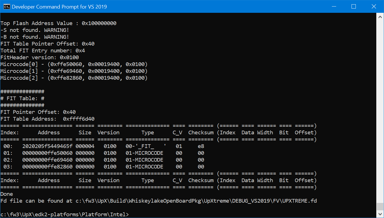
$ python3 build_bios -p UpXtreme -t VS2019
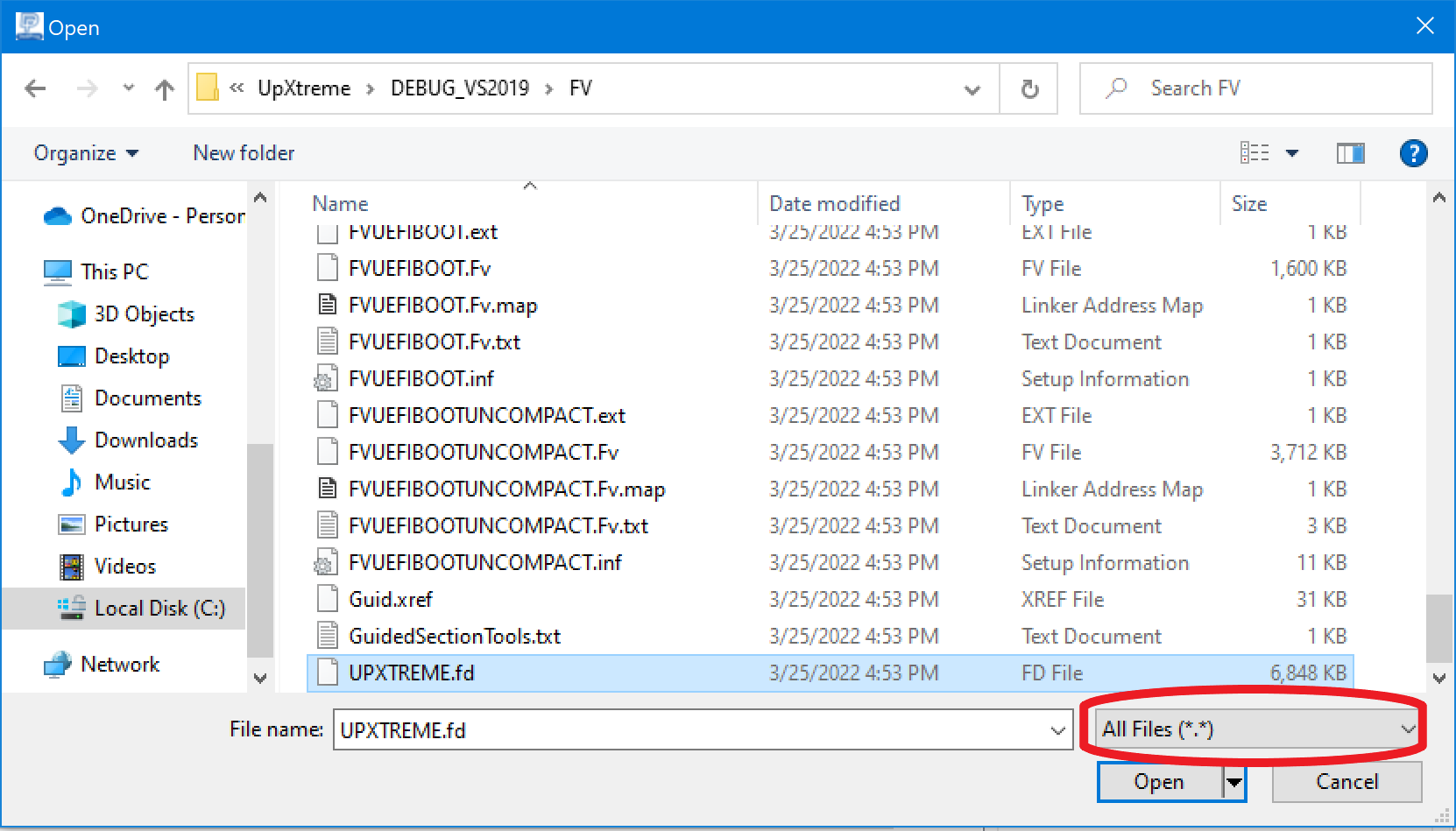
And, voila, in a little over three minutes (on my build machine; I’ve heard it take up to 20 minutes on slower machines), you have a 6,848kB UPXTREME.fd file in the
c:\fw\UpX\Build\WhiskeyLakeOpenBoardPkg\UpXtreme\DEBUG_VS2019\FV
folder:
Flashing the Image
Now, it’s time to flash the target with our new image!
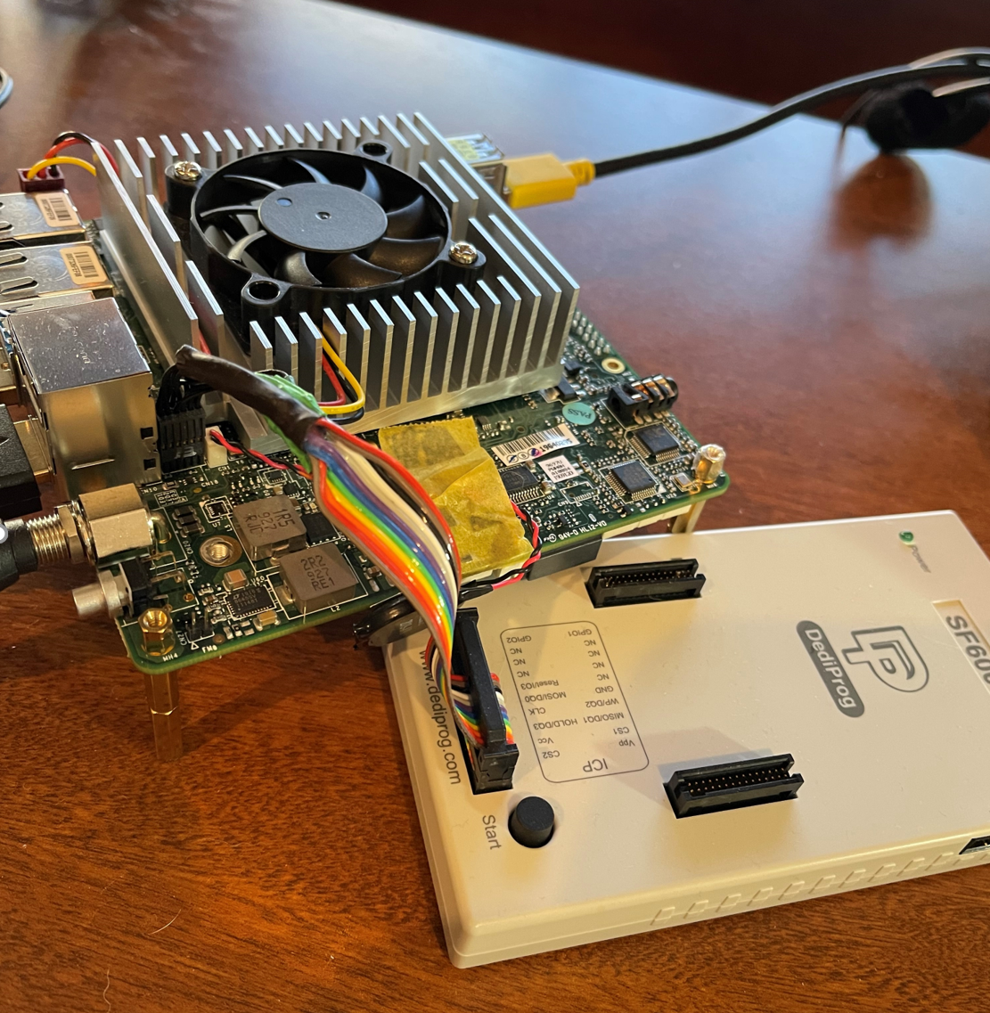
You’ll need a custom cable for the AAEON UP Xtreme board. The SPI flash header is a non-standard 12-pin, 2X6, and to the best of my knowledge, you can’t just buy one of these from DediProg or other companies. I had a custom cable made, and plugged it into the target:
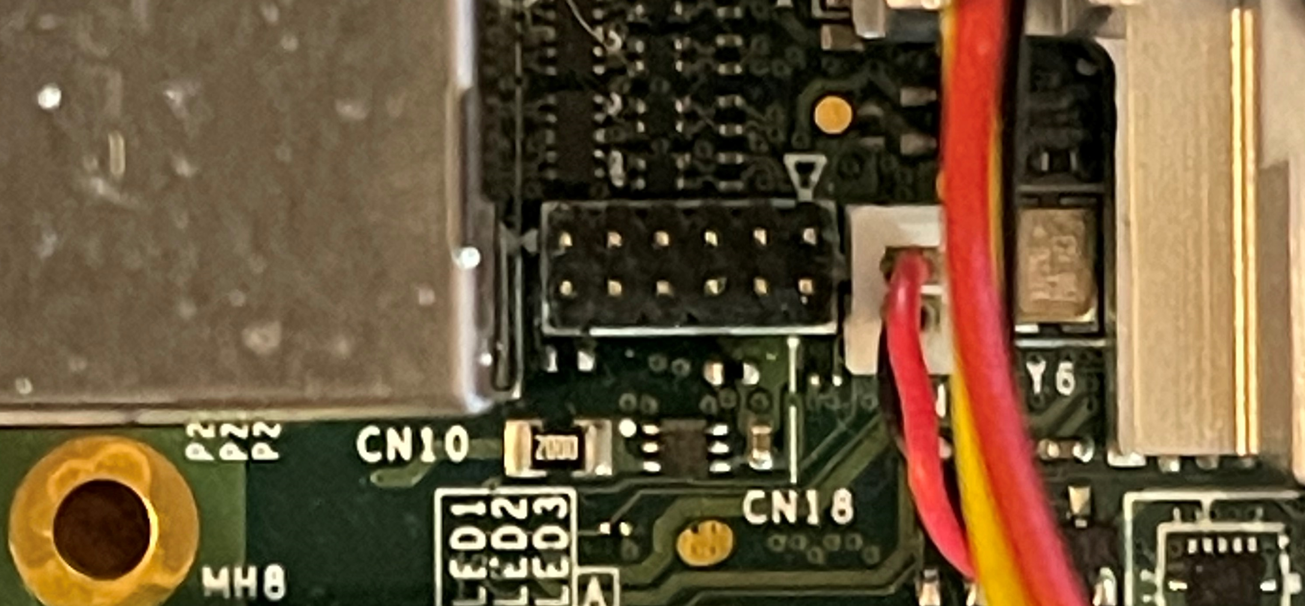
The SPI header is CN18 on the board. Note the triangle for pin 1, which should match up with the connector on your custom cable:
Once you’ve done all that, it’s time to flash the image, first with a Full Chip flash with UPW1AM18DassetFIXED.bin, and then a partial flash with your UPXTREME.fd. Note that I’ve used the DediProg SF-600; I have heard that the DediProg SF-100 won’t work with this device on this board.
It has to be stitched on top of the AAEON UPW1AM18D debug BIOS that is available on their website here:
https://downloads.up-community.org/download/up-xtreme-uefi-debug-bios-v1-8d/.
Note: at the time of writing, the Download button is a link on the right-hand side of the screen. You can almost miss it if you’re not looking carefully; I swear they move it around once in a while, for reasons of their own. AAEON, make the link more prominent, please!
There are a couple of tricks here to deal with before we flash. Firstly, the AAEON UPW1AM18D.bin (32,768 kB) base image BIOS has to be stitched to accommodate the UPXTREME.fd (6,848 kB) build that we did, and that means making some adjustments to the partition offsets in the base image. I’ll write about how to do that in a future blog, but in the meantime, you can pull down the adjusted UPW1AM18D.bin, appropriately named UPW1AM18DassetFIXED.bin, from the zip file on our website here: UPW1AM18DassetFIXED.
Secondly, there’s a run-control deficiency with the AAEON UP Xtreme Whiskey Lake board, the DbC3 access mechanism, and SourcePoint. If you power-cycle or reset the target, SourcePoint loses control; that is, run-control ceases to function. Now, normally this wouldn’t be an issue with routine debugging, but it’s common to want to reset the board, halt at the reset vector, and then debug in PEI or DXE portions of the image. We’re still trying to get to the bottom of this, but in the meantime, you have to use a creative workaround: within the DediProg Engineering application, you have to patch the UPW1AM18Dasset.bin image combined with your own UPXTREME.fd generated above to replace the two NOPs (x’90’) at the reset vector with a relative jump to itself: a JMP $ (hex EB FE), thereby creating a deadloop there.
Confused? Just follow the steps below:
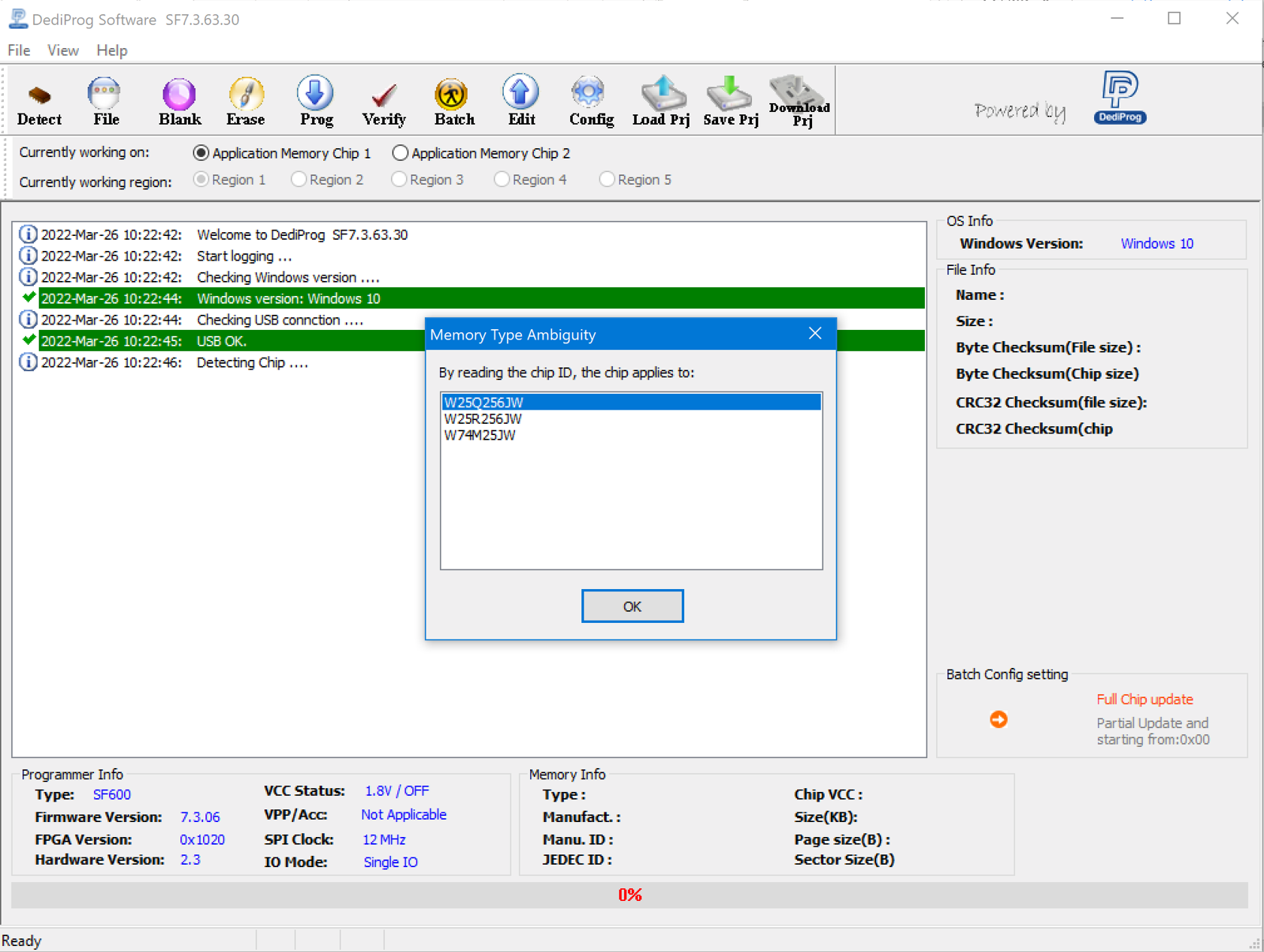
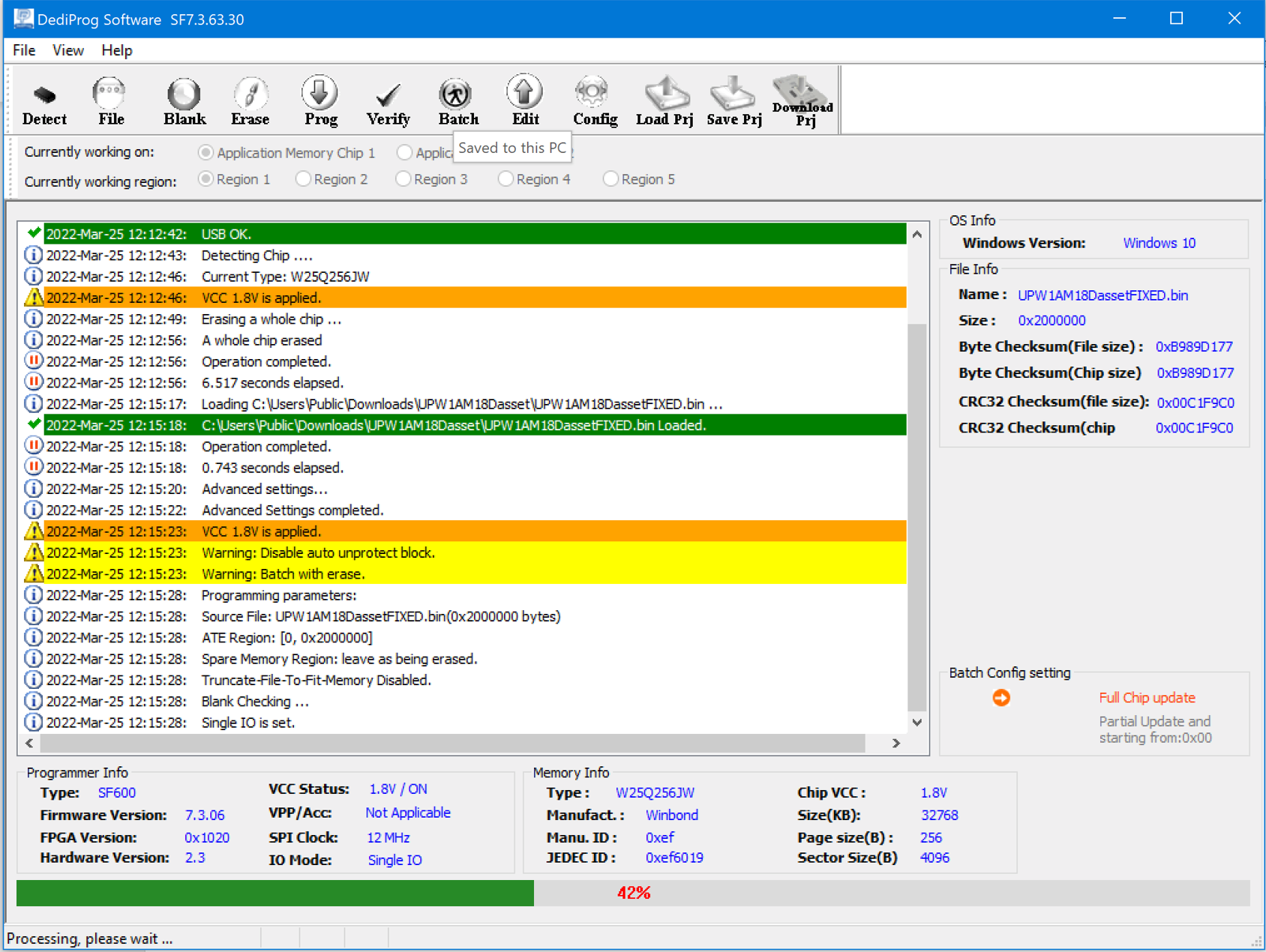
With the power completely off on the board (I unplug it), connect the programming cable to the target, then to your host PC USB port, and then launch the DediProg Engineering application. The part on the Whiskey Lake board is the W25Q256JW:
Hit the Erase button.
Then the File button, and choose UPW1AM18DassetFIXED.bin:
Hit the Config button, then select the Full Chip program:
Then hit the Batch button, and the program/verify will run. It takes about 150 seconds:
Now, it’s time to overlay your FD image on top of this.
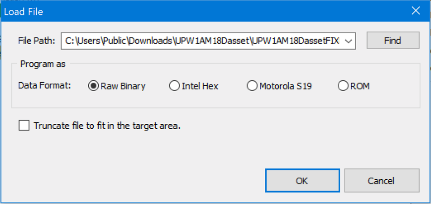
Select the File button, and pick your UPXTREME.fd image. Note you’ll need to change to “All Files” to pick up the .fd file.
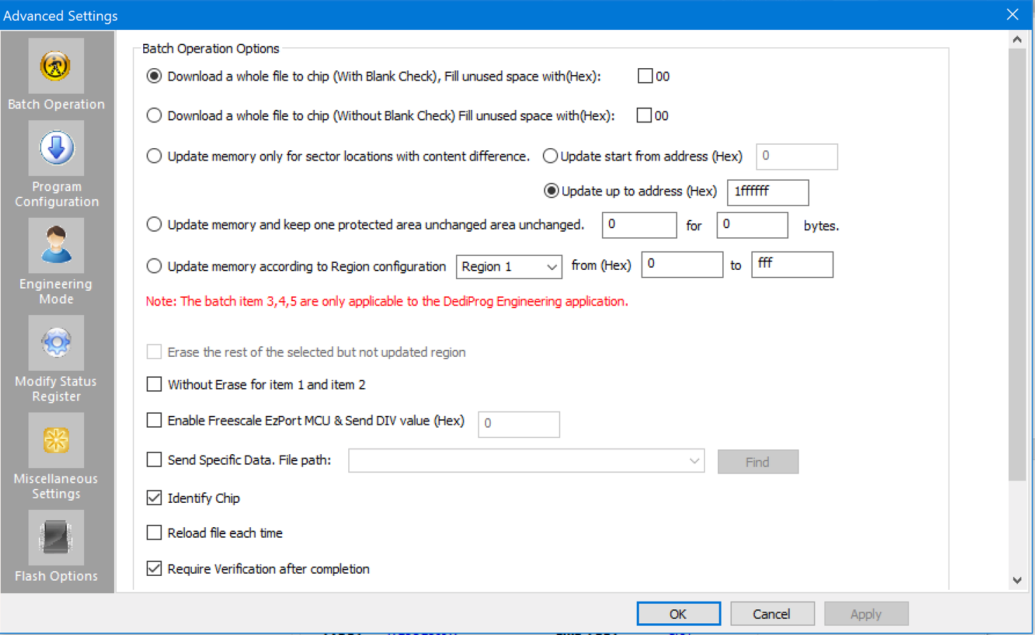
Then do Config, and select the upper bound of 1FFFFFF (decimal 33,554,431).
Then go ahead and do the Batch button, and begin the program/verify cycle again.
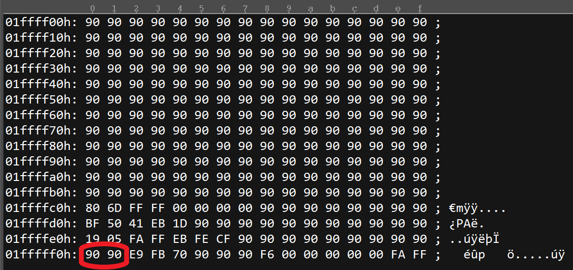
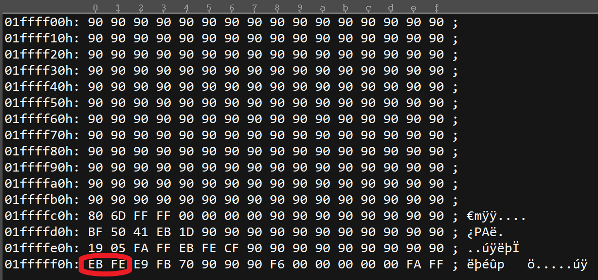
There’s one final step needed to create the deadloop at the reset vector. Click on the Edit button, do a Read, and then change the first two bytes (at 1FFFFF0 and 1FFFFF2) in the last line to EB FE, the hex equivalent to the JMP $ “jump to myself” instruction. Then save the resulting Chip Buffer to a file, and then do an Erase and a Full Chip programming again with this new file.
Finally! Starting Debugging
Close the DediProg Engineering application, and unplug the USB cable on the host PC side.
Plug in the specialty Type-A/A DCI USB cable to the host and target. Remember, these are not normal USB cables, but rather the ones with VBUS snipped that you need to purchase from DataPro or from Intel DesignInTools. Part # ITPDCIAMAM1M for the 1meter cable, and ITPDCIAMAM2M for the 2m cable.
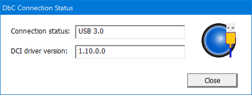
Launch the DbCStatus.exe in the SourcePoint installation directory. It will show up as red, since there’s no connection yet. In about 10 seconds, the ball will turn blue, indicating a successful DCI connection:
Plug the AAEON UP Xtreme board back in, and hit its Power button. It will power up, the fan will start spinning, but the screen will remain blank. That’s because you’re in a deadloop at the reset vector. Things are working as expected!
Time to launch SourcePoint, and create a Whiskey Lake project. This is easy, and I’m going to assume you know how to do this at this point. If not, check out our Getting Started Guide for the AAEON UP Xtreme i11 board for step-by-step instructions (the document refers to the AAEON Tiger Lake board, but the steps are similar). Hit the STOP button to halt the platform, and you’ll see the reset vector deadloop:
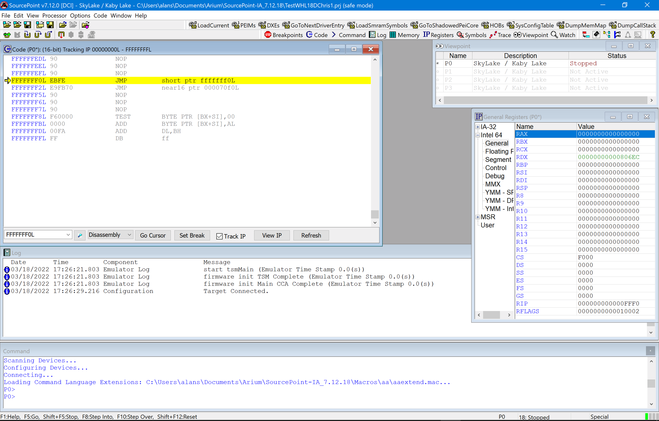
There’s a few ways to get out of the deadloop. One easy way is to put the cursor at FFFFFFF2L, right click, select “Set IP”, and it will jump to the FFFFFFF2 address. Then, run-control is fully operational. Use single-step, set breakpoints, hit GO and STOP, etc.
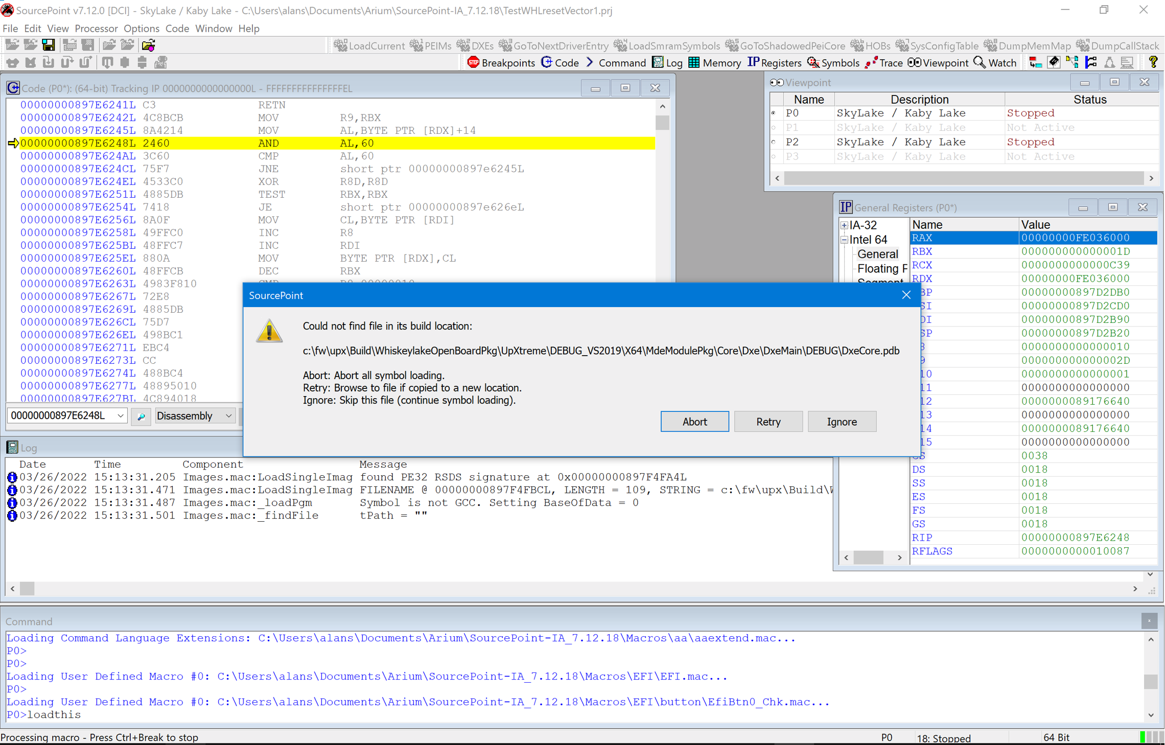
A quick example is hitting GO, waiting until the Tianocore splash screen shows up, and then hit STOP. You’ll be somewhere in DXE. If you want to see the source/symbols, you have to map the fully qualified path of where the image was built with what is on your host debug PC. After loading the UEFI macros, click on the LoadCurrent button, and then hit Retry within the dialog box that tells you about the path mismatch:
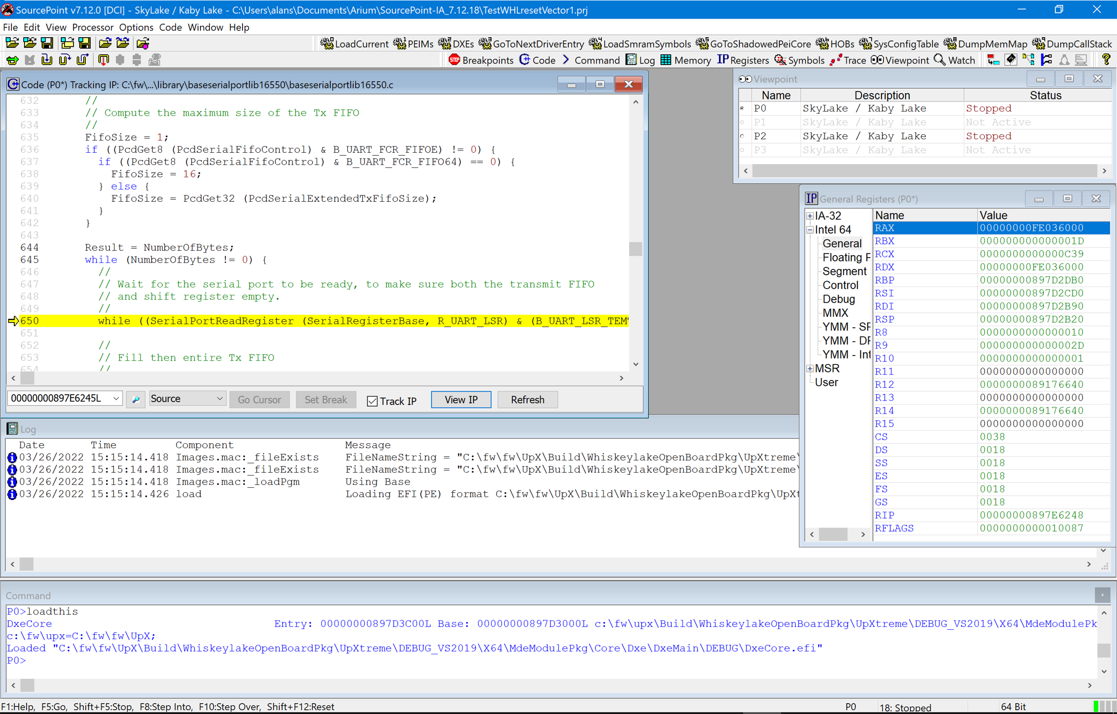
Mouse your way over to the actual build directory on your host PC, which in this case could be:
C:\fw\fw\UpX\Build\WhiskeylakeOpenBoardPkg\UpXtreme\DEBUG_VS2019\X64\MdeModulePkg\Core\Dxe\DxeMain\DEBUG
Then, select this file, and voila, you see the source code:
You can also click on the PEIMs and DXEs buttons at the top to load source/symbols for all of PEI and DXE loaded modules. It takes a couple of minutes, but it gives you access to the whole source tree at your fingertips.
NOTE: There’s one deficiency, at the time of this writing, that needs to be resolved: this build will never get to the UEFI shell. When you hit GO, some rogue code kicks in and you go back to the reset vector deadloop, instead of to the UEFI shell as expected. And the second time, there is no escape; you have to power-cycle the board to start UEFI debug all over again. Ah, the joys of UEFI debug combined with JTAG combined with nasty parts of code that try to get in between them.
I hope that this has been helpful. It is nice that now JTAG debug on somewhat affordable hardware is available to more people. It’s a tremendous learning experience for those interested in the “on the metal” interactions between x86 architecture and low-level firmware. This has been available on Arm for a long time; we need more people graduating from school with a deep knowledge of the foundation of what constitutes most of our daily driver computers today.
Want to learn more? For a limited time, we are making low-cost versions of SourcePoint for Intel available to individual hobbyists, researchers and academic institutions. For more information, go here: SourcePoint Intel Limited Time Offer.