
To commence Boundary Scan testing on a UUT, the first step is to ensure that all the Boundary Scan devices on our PCB are operating correctly. The Boundary Scan devices must be capable of executing all Boundary Scan instructions specified by the IEEE 1149.1 standard.
Mandatory instructions such as EXTEST and BYPASS are important instructions the Boundary Scan devices must execute without issue. One important optional instruction is OPCODE. You should always attempt to use Boundary Scan devices on your UUT that support the IDCODE instruction. (Read more about mandatory and optional Boundary Scan instructions in part 3 of this blog series.)
If the Boundary Scan devices are not capable of executing these instructions correctly, the ScanWorks test actions we build, when applied to the UUT, will return incorrect data back to ScanWorks.
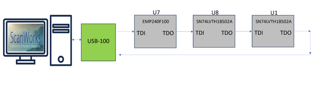
As ScanWorks controls each device, moving it through the Capture, Shift, and Update states, data is shifted into the Scan Chain of the UUT via TDI. Data is eventually received back at ScanWorks via TDO, where it is compared to the data that is expected to be received back from the UUT. If there are bits in the data stream that do not compare (mis-compare), ScanWorks identifies the mis-compared bits. We’ll discuss mis-compared bits and debugging in a future blog.
A benefit of using ScanWorks for Boundary Scan testing is that the test actions can be developed prior to the physical UUT being available. ScanWorks requires the input files we’ve discussed, such as the BSDLs, to create the Scan Path. There are other files that we haven’t yet discussed, such as the UUT netlist, programming models, and memory models to build other test actions (i.e., Interconnect, Flash, and Memory Access Verify). We’ll discuss these files and action types in future blogs. When these files are available, they are imported into ScanWorks, and test actions can be developed. ScanWorks project development could occur months before a physical UUT has been produced and is available to the test engineer.
Let’s step through the process of building a Boundary Scan chain.
From this point forward in the blog series, I’ll reference the Boundary Scan devices and their BSDLs associated with ASSET’s ScanLite2 demonstration UUT. This demonstration UUT is used as a target during our 4-Day Boundary Scan Workshop where we train test and manufacturing engineers on the use of ScanWorks. The ScanLite2 can also be used to sanity-check test system prior to Boundary Scan testing.
We’ll build a Boundary Scan chain that consists of 3 devices:
- EPM240F100Altera MAX II CPLD – U7
- Texas Instruments TI SN74LVTH18502A (JTAG) Boundary-Scan Test Device with 18-Bit Universal Bus Transceivers – U8, U1
Description of the Scan Chain
 Before starting this process, a little prep work is necessary.
You must obtain the BSDLs for the Boundary Scan devices on your UUT. Obtaining the BSDLs can be a simple task, or it might involve some work on your part. Most often, you can simply go to the manufacturer’s website and download the appropriate BSDL files. It can become a bit difficult if you need to register and submit a non-disclosure Agreement or (NDA) to obtain the BSDLs. (For the ASSET 4-day Boundary Scan Workshop, the BSDLs for the Boundary Scan devices on the ScanLite2 are supplied.)
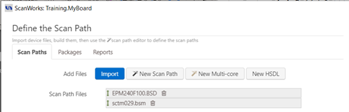
Once you obtain the BSDLs, you’ll Import the BSDLs into ScanWorks and select the Build button. As I refer to the test action process, I’ll refer to the Build button.
When ScanWorks builds, it compiles imported files and makes them ready for use within ScanWorks. When ScanWorks builds the BSDLs, it checks the BSDLs for syntax and semantics errors. You may ask the question “What happens when an error is found during the build of a BSDL?” ScanWorks will identify when an error is detected along with the line number and error information. We’ll discuss BSDL syntax and semantics errors in a future blog.
Once the BSDLs have been built properly, and no syntax or semantics errors are detected, we must arrange the built BSDLs in the order of their corresponding Boundary Scan devices on the UUT. The order of the Boundary Scan devices is important. The Boundary Scan devices are described to ScanWorks beginning with the Boundary Scan devices closest to the UUT TDI input down to the Boundary Scan device nearest to the UUT TDO output.
This is where your prep work comes into play. To describe the Scan Chain to ScanWorks properly, you must know the proper TDI to TDO order.
You may get the TDI-TDO order from the board designer. Or maybe the board designer has provided a block diagram of the Scan Chain order. The UUT schematic can be helpful as well but can be a bit more time-consuming to trace out the Scan Path. The Bill of Materials is helpful as well. Parts come in many packages; you’ll need to know which Boundary Scan device package types you have on your UUT.
Once you know the Scan Chain order, you’ll use Design Wizard to place the devices in order, TDI to TDO, you may wonder “What if I describe the scan chain incorrectly and how will I know this?” This topic will be covered in a future blog.
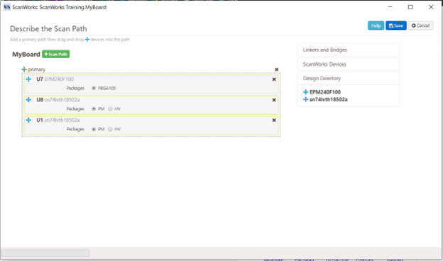
Once you’ve described the Boundary Scan chain, you’ll see the following on the main ScanWorks user interface.

Next, we’ll create a Scan Path Verify action.
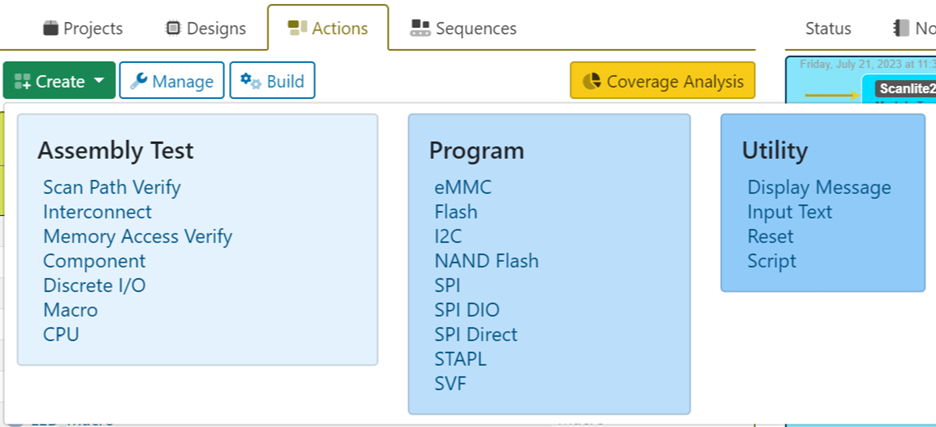
ScanWorks has a list of standard action types under the Actions tab. The Actions are grouped into 3 categories: Assembly Test, Program, and Utility.
The Scan Path Verify action runs each of these operations in the order listed in the described Scan Chain.
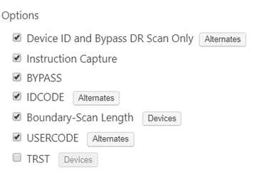
| Option | Description |
| Device ID and Bypass ID | Device ID and Bypass DR Scan only test all components in the scan path. The initial action reset places the Device ID or Bypass register in the scan path for each device. A DR scan is done to check that the correct value from the ID code or Bypass register matches those defined in your BSDL description, in the order described in the scan path. The Alternates... button allows you to specify alternate ID codes that are valid for this design. |
| Instruction Capture | Instruction Capture checks the instruction register capture value for all components in the scan path using IR scans with the BYPASS instruction. This verifies that the instruction register for each device is functioning correctly. |
| BYPASS | BYPASS checks the TDI, TDO, TMS, and TCK signals in your scan path. An IR scan is done while devices are put into BYPASS during this test. A DR scan pattern containing zeros and ones is done. |
| IDCODE | IDCODE tests all components that implement the IDCODE instruction. This verifies that the devices with ID codes match those defined in your BSDL description. If the component does not support the IDCODE instruction, this test uses the BYPASS instruction to check the value captured from the bypass register.
The Alternates… button allows you to specify alternate ID codes that are valid for this design and to select which codes will be checked for a match. The test passes if the device ID code matches any of the specified ID codes. If no ID codes are selected, the code read is compared to the ID code specified in the BSDL. |
| Boundary-Scan Length | Boundary-Scan Length checks the length of the boundary-scan register for each device in the scan path.
Each device is put into SAMPLE/PRELOAD with all other devices put into BYPASS. DR scans are done with a pattern of zeros and ones and a large amount of overshifting. An option in the Test Results dialog allows the entire set of scan data to be viewed. The Devices… button allows you to specify which devices to exclude from the test, marked by the checkbox. |
| USERCODE | USERCODE tests all components that implement the USERCODE instruction. This verifies that the devices with user codes match those defined in your BSDL description or configured into the device.
The Alternates… button allows you to specify alternate user codes that are valid for this design and to select which codes will be checked for a match. If no user codes are selected, the code read is compared to the user code specified in the BSDL. The test passes if the device user code matches any of the user codes included, marked by the checkbox. |
| TRST | TRST tests the proper functioning of the TRST of the user-specified devices one at a time. All devices in the scan path that implement the TRST pin are selected as a default when TRST is selected. You can change the devices specified using the Devices… button. Each device to be tested is put into SAMPLE. Other devices that support IDCODE will get an IDCODE instruction. Remaining devices will get a BYPASS instruction. ScanWorks asserts TRST and verifies the data captured from the device ID or bypass register as appropriate. |
Once the Scan Path Verify action is built, the test can be applied with a single click of the arrow or Run button within the action.
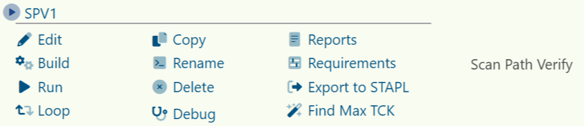
Once the Scan Path Verify is built, several options are available such as Edit, Loop, Copy, Rename, and Debug.
In the next blog, I’ll discuss how ScanWorks identifies BSDL syntax and semantics errors and Scan Path Verify failures encountered when running the test action.