
With IEEE 1687 (aka IJTAG) making its way into a great many chips as a mainstream mechanism for access and control of embedded instrumentation, I’ve taken an interest in explaining this often complicated technology in simple terms. I’ll start with describing the syntax, semantics and overall structure of Instrument Connectivity Language (ICL) and Procedural Description Language (PDL).
IEEE 1687, which was approved as a Standard by the IEEE in 2014, was created to facilitate use of semiconductor internal instrumentation in a consistent way. Prior to this standard, each chip supplier used its own proprietary approach to provide access and control to instruments such as memory built-in self test (MBIST), I/O BIST, logic BIST, embedded sensors, power controllers, etc. Thus, scaling the use of these instruments to board and system environments was extremely difficult. Tool providers had to develop and deliver proprietary solutions for every chip manufacturer, device, and BIST. Thus, the advent of IJTAG promised a brighter future for the reuse of BIST and chip Design for Test (DFT) by more stakeholders. Widespread use of standardized BIST interfaces across the product lifecycle promised more insight into root cause of system issues and was considered a landmark accomplishment when the standard was approved.
But, as with many technologies, there’s been quite a time lag between declaration of the standard (2014) and the present day. Although we deal with some of the most advanced technologies on the planet, there is a lot of inertia within chip design. Tried and true methods are used and re-used. The 1687 Standard is very complex, as it tries to maintain a level of compatibility with known chip designs. And the EDA suppliers, who deliver the tools used to design these chips, are slow to speculate on new technologies without proven business cases and customer demand. But now, to a great extent driven (as far as I can tell) by the mainlining of IJTAG support by Mentor (Siemens EDA), and widespread adoption by the major semiconductor companies, its future seems assured.
Support for IJTAG consists of the silicon logic delivered by the EDA suppliers’ chip design applications, as well as test, debug and platform validation tools developed by the tools suppliers such as ourselves.
From a tools perspective, a key deliverable from the EDA software are ICL and PDL files, that describe the IJTAG network and how to access and control the instruments therein.
To illustrate the use of these output ICL and PDL files, we’ve created a small ScanWorks IJTAG project that does one simple thing: it lights up an LED connected to a Xilinx Spartan-6 FPGA on the Opal Kelly XEM6002 evaluation board (which is, unfortunately, very hard to find nowadays). Although the application seems trivial, the project demonstrates a full implementation of IEEE 1687: it configures the FPGA with an IJTAG network that provides access to the LED “instrument”, it loads the full network description and instrument access and control into the ScanWorks database, and it allows the direct execution of the IJTAG-based procedures (iProcs) needed to read and write to the instrument.
Before we dive down into the PDL and ICL languages, a few pictures will help illustrate some of the technical underpinnings of IJTAG.
The XEM6002 looks like this:
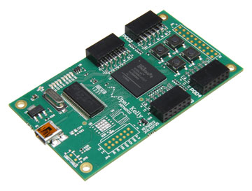
This simple board has eight LEDs, that are connected to the Xilinx Spartan-6.
JTAG access is provided directly, and the scan chain on the board looks very simple:
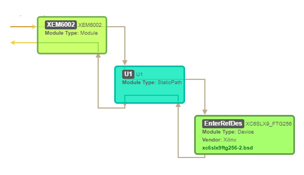
XC6SLX9_FTG256 is the “entity name” of the Spartan-6, which is derived from its BSDL file.
Finally, the IJTAG Network, or instrumentation map, looks like this:
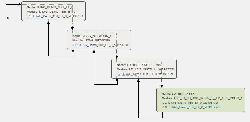
It will help to refer back to these maps when we look at the ICL language description of the network.
Procedural Description Language (PDL)
To see how this all fits together, let’s look at PDL first, and review a very simple example:
iProcsForModule BST_IO_LD_1Bit_Instr_1__LD_1Bit_Instr_1

iProc write_input { DATA } {

    iWrite xi_LD0 $DATA ;

    iApply;

       iRunLoop -time 2000;

}

iProc read_output { EXP } {

    iRead LD0 $EXP ;

    iApply;

    puts $EXP

}

iProc puts_read_output { EXP } {

    iRead LD0 $EXP ;

    iApply;

    set output [iGetReadValue LD0] ;

    set expected 0b$EXP ;

    if { $output != $expected } {

        iSetFail "iSetFail: Failing action since actual does not match expected" ;

        iNote -comment "*** LD0: Expected = $expected, Actual = $output ***" ;

    }

}
The main function of PDL is to describe the operations available on the instruments that are accessible via the IJTAG network.
PDL comes in two levels: level-0 and level-1, with the former being a subset of the latter. Level-0 contains the basic commands to perform operations on embedded instruments. Level-1 adds some additional commands, and also is prescribed to be run (primarily) under Tcl, which can support the use of conditional logic, looping, branching, and other constructs of a high-level programming language.
The commands available under Level-0 support are:
| Command | Type | Parameters | Purpose |
| iApply | Action | [ -together ] | Execute queued read, write and scan operations |
| iCall | Setup | hierProcName (arguments)* | Invoke a PDL procedure |
| iClock | Setup | ClockPort | Specify a system clock, which is required to be running |
| iClockOverride | Setup | ToClockPort ‘-source’ clockPort -freqMultipler mult -freqDivider div -period int [unit] | Override definition of system clock when it is generated on-chip |
| iMerge | Setup | -begin | -end | Allow merging (concurrent evaluation) of iCalls |
| iNote | Action | -comment | -status text | Send text to runtime |
| iOverrideScanInterface | Setup | <scanInterface_name> -captureEn (on) | off -updateEn (on) | off -broadcast on | (off) | Indicate the capture, update, and broadcast behavior to be imposed on a list of scan interfaces |
| iPDLLevel | Setup | (‘0’ | ‘1’) ‘-version STD_1687_2014’ | Identify PDL Flavor |
| iPrefix | Setup | instance_path | Specify hierarchical prefix |
| iProc | Setup | procName ‘{‘ arguments* ‘}’ ‘{‘commands+’}’ | Wrapper for a PDL procedure |
| iProcsForModule | Setup | [namespace::]moduleName – iProcNameSpace nameSpace_name | Identify the module in the ICL with which subsequent iProcs are associated |
| iRead | Setup | (register | port | alias) value | Queue data to be read |
| iRelease | Setup | instance | register | port | Re-allow other merge threads to modify a model resource |
| iReset | Action | ‘-sync’? | Reset the network |
| iRunLoop | Action | ( cycleCount ( ‘-tck’ | ‘-sck’ port )? | ‘-time’ tvalue | Issue a number of clocks. tvalue is in milliseconds |
| iScan | Setup | scanInterface_name ‘-ir’? length ‘-si’ siData ‘-so’ soData | Queue data to be scanned |
| iState | Action | reg|port value -LastWrittenValue | -LastReadValue | -LastMiscompareValue | Document the current state of the network |
| iTake | Setup | instance | register | port | Disallow other merge threads from modifying a model resource |
| iUseProcNameSpace | Setup | nameSpace_name | Use namespace for subsequent iCalls |
| iWrite | Setup | (register | port | alias) value | Queue data to be written |
And the additional commands available in level-1 are:
| Command | Parameters | Purpose |
| iGetMiscompares | register | port | alias | ScanInterface [-bin | -hex | -dec] | Return (as a string in the specified unsized number format) the XOR of the value from the most recently applied iRead operation on a register or output port (or an alias consisting of either or both) and the value expected for that iRead operation. May contain x-values. |
| iGetReadData | register | port | alias | ScanInterface [-bin | -hex | -dec] | Return (as a string in the specified unsized number format) the value from the most recently applied iRead operation on register or output port (or an alias consisting of either or both). May contain x-values. |
| iGetStatus | [-clear] | Return the decimal number of iApply miscompares that have occurred since the last time that iGetStatus -clear was issued. Clear the count afterwards if directed. |
| iSetFail | message [-quit] | Return the message string to the controlling program to indicate an unexpected condition, with the optional directive to abort execution. |
Thus, referring back to our simple PDL code above, we note that we use a mix of level-0 commands (iRead, iWrite, iApply, iRunLoop, and iNote), as well as level-1 (iSetFail). We also use Tcl (as in the “if” statement, “puts”, etc.). Thus, this is an example of level-1 PDL.
Also note that the command:
iProcsForModule BST_IO_LD_1Bit_Instr_1__LD_1Bit_Instr_1
identifies:
BST_IO_LD_1Bit_Instr_1__LD_1Bit_Instr_1
as the module in the ICL to which the iProcs listed below:
write_input

read_output
and
puts_read_output
apply.
Whew!
This will all make sense when we look at the ICL for this project.
Instrument Connectivity Language (ICL)
The purpose of ICL is to describe the behavior of the network of instrumentation within a chip in a standard way.
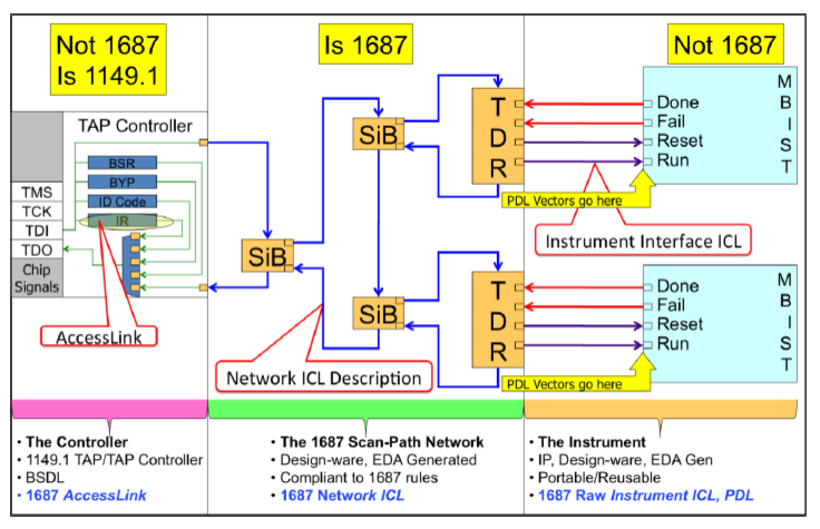
An overview of the IJTAG hardware architecture is as below:
To understand ICL, it’s first important to grasp how the instrumentation network is described, what make up its building blocks, and the statements, grammar, and reserved words of the language. A complete description is beyond the scope of this blog. But, I’ll describe enough of it to understand our example project.
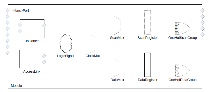
The fundamental entity within ICL is called a Module. The building blocks that make up a Module can be seen visually from Figure 39 of the IEEE 1687 specification:
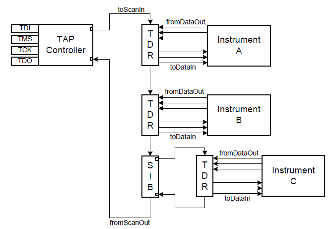
And, a simple diagram of a three-instrument, variable-length scan chain is below. Note that the Segment Insertion Bit (SIB) at the bottom, when ‘0’, and its Test Data Register (TDR) is excluded. When set to ‘1’, the SIB is considered to be in an open state, and its TDR data is inserted into the scan chain:
Let’s keep these visuals in mind. It’ll come together once we look at the associated ICL for our project, and describe the major aspects thereof. There are some comments in the ICL to make it easier to navigate and understand:
// The Instrument to be Tested

Module BST_IO_LD_1Bit_Instr_1__LD_1Bit_Instr_1

{

    DataInPort xi_LD0;

    DataOutPort LD0;

}

// SIB/TDR Unit: Contains an instance of the Instrument to be Tested,

//   the Test Data Register (TDR) associated with the Instrument, and

//   the SIB used to insert the TDR data into the Scan Chain.

Module LD_1Bit_Instr_1__Wrapper

{

    // Scan Chain associated ports:

    ScanInPort TDI;

    ScanOutPort TDO { Source SIB_mux; }

    // Instrument associated port:

    DataOutPort LD0 { Source LD_1Bit_Instr_1.LD0; }

    // Instance of the Instrument to be Tested:

    Instance LD_1Bit_Instr_1 Of BST_IO_LD_1Bit_Instr_1__LD_1Bit_Instr_1 {

        InputPort xi_LD0 = Write_TDR[0];

    }

    // The Test Data Register (TDR) associated with the Instrument:

    ScanRegister Write_TDR[0] {

        ResetValue 1'b0;

        ScanInSource SIB;

        CaptureSource LD_1Bit_Instr_1.LD0[0];

    }

    // The ScanRegister and ScanMux, collectively, comprise the SIB

       // (Segment Insertion Bit).  When the value of SIB is '0', the

       // SIB is considered "closed" and the TDR data cannot be accessed.

       // When the SIB is '1', the SIB is considered "open" and the TDR

       // data is inserted into the Scan Chain.


       // -- The SIB bit

    ScanRegister SIB {

        ResetValue 1'b0;

        ScanInSource TDI;

        CaptureSource SIB;

    }


    // -- The SIB MUX

    ScanMux SIB_Mux SelectedBy SIB {

        1'b0 : SIB;

        1'b1 : Write_TDR;

    }

}


// This Module defines the Scan Chain which includes any module

// instances that consist of Instrument TDRs and SIBs for accessing

// those TDRs.

Module IJTAG_Network

{

    // Scan Chain associated ports

    ScanInPort TDI;

    ScanOutPort TDO { Source SIB_Mux; }


    // Instrument associated port

    DataOutPort LD_1Bit_Instr_1___LD0      { Source LD_1Bit_Instr_1__W1.LD0; }


    // The short Scan Chain network includes this instance of the module

       // LD_1Bit_Instr_1__Wrapper/

    Instance LD_1Bit_Instr_1__W1 Of LD_1Bit_Instr_1__Wrapper {

        InputPort TDI = SIB;

    }


    // The ScanRegister and ScanMux, collectively, represent a top-level

       // SIB which, when closed ('0') hides any SIBs that come after it,

       // such as the one associated with LD_1Bit_Instr_1__Wrapper.


       // -- The SIB bit

    ScanRegister SIB {

        ResetValue 1'b0;

        ScanInSource TDI;

        CaptureSource SIB;

    }


    // -- The SIB MUX

    ScanMux SIB_Mux SelectedBy SIB {

        1'b0 : SIB;

        1'b1 : LD_1Bit_Instr_1__W1.TDO;

    }

}


Module IJTAG_Demo_1Bit_ET_0

{

    // Scan Chain associated ports

    ScanInPort BSCAN_SPARTAN6_tdi;

    ScanOutPort BSCAN_SPARTAN6_tdo { Source IJTAG_Network_1.TDO; }


    // Instrument associated port

    DataOutPort K2 { Source IJTAG_Network_1.LD_1Bit_Instr_1___LD0; }


       // Instance of the module IJTAG_Network which defines the

       // Scan Chain

    Instance IJTAG_Network_1 Of IJTAG_Network {

        InputPort TDI = BSCAN_SPARTAN6_tdi;

    }


       // The Scan Interface Declaration: this defines the Scan In

       // and Scan Out ports for accessing the Scan Chain.

    ScanInterface BSCAN_SPARTAN6_Gateway { Port BSCAN_SPARTAN6_tdi; Port BSCAN_SPARTAN6_tdo; }


       // The Access Link Declaration: this provides the conduit between

       // the Test Access Point (TAP) and the Scan Interface and

       // includes the Instrument Register command taken from the BSDL

       // file for opening the Scan Chain (in this case, "USER1" with

       // a value of 0b000010).

    AccessLink Tap_1149_dot_1 Of STD_1149_1_2001 {

        BSDLEntity XC6SLX9_FTG256;

        USER1 {

            ScanInterface { IJTAG_Demo_1Bit_ET_0.BSCAN_SPARTAN6_Gateway; }

        }

    }

}
As you can see, the ICL is longer and a bit more complex than the associated PDL.
Let’s take a look at some of the individual sections to make this easier to understand; starting with the Module at the bottom, IJTAG_Demo_1Bit_ET_0.
Starting at the very bottom, we see the AccessLink instruction that describes the connection between the external IEEE 1149.1 TAP and the 1687 network:
AccessLink Tap_1149_dot_1 Of STD_1149_1_2001 {

BSDLEntity XC6SLX9_FTG256;

USER1 {

ScanInterface { IJTAG_Demo_1Bit_ET_0.BSCAN_SPARTAN6_Gateway; }

}

}
In this case, the AccessLink instruction refers to the BSDLEntity XC6SLX9_FTG256. This is the Entity name of the Spartan-6 FPGA within its BSDL.
USER1 is a private instruction within the Spartan-6’s BSDL that provides access to the scan path. Here’s an excerpt from the FPGA’s BSDL:
attribute INSTRUCTION_OPCODE of XC6SLX9_FTG256 : entity is

"EXTEST      (001111)," &

"SAMPLE      (000001)," &

"PRELOAD     (000001)," & -- Same as SAMPLE

"USER1       (000010)," & -- Not available until after configuration
So, to open up the scan path to the internal instrumentation, we need at some point to write binary 000010, x’02, to the TAP Instruction Register.
For the USER1 instruction, the associated ScanInterface exists in our module IJTAG_Demo_1Bit_ET_0 (you’ll see that by scrolling up a little bit from the AccessLink instruction), and the connection point to the network is through BSCAN_SPARTAN6_Gateway, which in turn is defined in the ICL by:
ScanInterface BSCAN_SPARTAN6_Gateway { Port BSCAN_SPARTAN6_tdi; Port BSCAN_SPARTAN6_tdo; }
The scan chain TDI port is BSCAN_SPARTAN6_tdi, and the TDO port BSCAN_SPARTAN6_tdo. Note that these names occur in:
InputPort TDI = BSCAN_SPARTAN6_tdi;
and
ScanInPort BSCAN_SPARTAN6_tdi;
and
ScanOutPort BSCAN_SPARTAN6_tdo { Source IJTAG_Network_1.TDO; }
And the instrument port is defined by:
DataOutPort K2 { Source IJTAG_Network_1.LD_1Bit_Instr_1___LD0; }
Pin K2 on the Spartan-6 (ScanWorks knows which one this is) is connected to the associated LED that we’re going to be turning on and off.
When all this is read into ScanWorks’ database, the entire topology of the IJTAG network is known, and we can access the LED instrument directly through its fully qualified IJTAG path. For example, to turn on the LED, we perform this within a ScanWorks Action:
XC6SLX9_FTG256.IJTAG_DEMO_1BIT_ET_0.IJTAG_NETWORK_1.LD_1BIT_INSTR__W1.LD_1BIT_INSTR_1.BST_IO_LD_1BIT_INSTR_1__LD_1BIT_INSTR_1::write_input(DATA=0b1)
That’s awesome!
Each of the fields within this ScanWorks Action operation is described below:
XC6SLX9_FTG256 is the entity name of the Spartan-6 FPGA.
IJTAG_DEMO_1BIT_ET_0 defines the TAP side of the AccessLink interface.
IJTAG_NETWORK_1 is our instance of IJTAG_Network (second from the top layer) that defines the IJTAG side of the AccessLink interface.
LD_1BIT_INSTR__W1 is our instance (an occurrence) of the wrapper module LD_1Bit_Instr_1__Wrapper that contains the instrument, its TDR, and its associated SIB. Note: don’t worry too much about what the two underscores (‘__’) signify; it’s just a convention that we use to signify a layer of hierarchy in some cases.
LD_1BIT_INSTR_1 is the instance of our instrument BST_IO_LD_1BIT_INSTR_1__LD_1BIT_INSTR_1.
BST_IO_LD_1BIT_INSTR_1__LD_1BIT_INSTR_1 is the module that describes the instrument. In this simple example, this is just a one-bit register. As can be seen by comparing the ICL and the PDL, its DataInPort is commonly called xi_LD0, and its DataOutPort is LD0, where xi_LD0 is the pin connected to the scan path, and LD0 goes to the LED.
If we go back to the PDL to see what’s happening when this ScanWorks action is run, the write_input(DATA=0b1) iProc just does an iWrite of “1” followed by an iApply. Then “iRunLoop -time 2000” will add a delay of two seconds before control returns back to the ScanWorks Action. After that, we could add any other additional operation that we wanted to, for example to do an iWrite of “0” which would turn the LED off.
Hopefully this has been helpful for those wanting a deeper understanding of IJTAG, and its associated ICL and PDL languages. To learn more about IJTAG, feel free to register for our IJTAG Tutorial, Third Edition eBook.