
Let’s continue analyzing the errors produced when running the Scan Path Verify action with more options selected. (To read Part 8, “BSDL Syntax and Semantics Errors and Scan Path Verify Failures”, click this link.)
The remaining 4 Scan Path Verify options.
The Scan Path Verify action runs each of the operations below in the order listed on the Describe Scan Path user interface.
- IDCODE
- Boundary-Scan Length
- USERCODE
- TRST
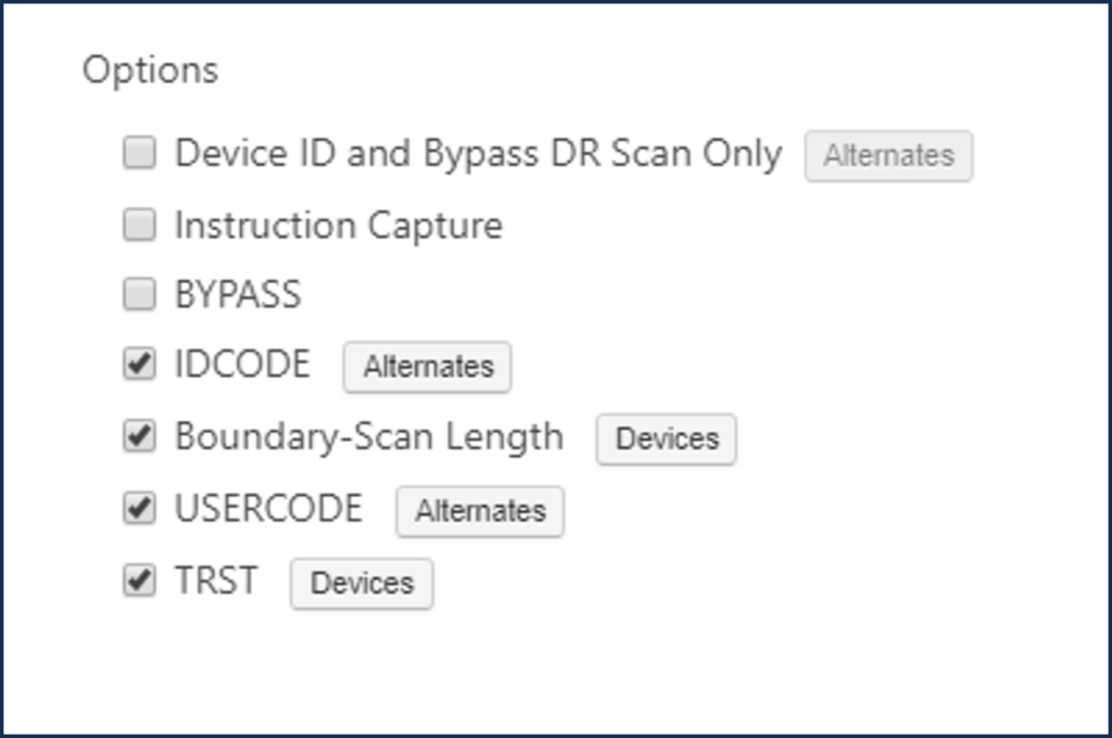
As a reminder, here is a description of the remaining 4 options. The options can be selected and run individually, or run all at once.
| Option | Description |
| IDCODE | IDCODE tests all components that implement the IDCODE instruction. This verifies that the devices with ID codes match those defined in your BSDL description. If the component does not support the IDCODE instruction, this test uses the BYPASS instruction to check the value captured from the bypass register.
The Alternates… button allows you to specify alternate ID codes that are valid for this design and to select which codes will be checked for a match. The test passes if the device ID code matches any of the specified ID codes. If no ID codes are selected, the code read is compared to the ID code specified in the BSDL. |
| Boundary-Scan Length | Boundary-Scan Length checks the length of the boundary-scan register for each device in the scan path.
Each device is put into SAMPLE/PRELOAD with all other devices put into BYPASS. DR scans are done with a pattern of zeros and ones and a large amount of overshifting. An option in the Test Results dialog allows the entire set of scan data to be viewed. The Devices… button allows you to specify which devices to exclude from the test, marked by the checkbox. |
| USERCODE | USERCODE tests all components that implement the USERCODE instruction. This verifies that the devices with user codes match those defined in your BSDL description or configured into the device.
The Alternates… button allows you to specify alternate user codes that are valid for this design and to select which codes will be checked for a match. If no user codes are selected, the code read is compared to the user code specified in the BSDL. The test passes if the device user code matches any of the user codes included, marked by the checkbox. |
| TRST | TRST tests the proper functioning of the TRST of the user-specified devices one at a time. All devices in the scan path that implement the TRST pin are selected as a default when TRST is selected. You can change the devices specified using the Devices… button. Each device to be tested is put into SAMPLE. Other devices that support IDCODE will get an IDCODE instruction. Remaining devices will get a BYPASS instruction. ScanWorks asserts TRST and verifies the data captured from the device ID or bypass register as appropriate. |
Demonstrating the error messages produced by ScanWorks.
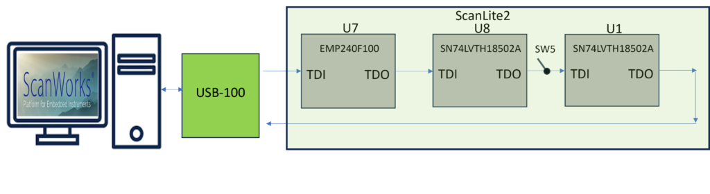
To demonstrate the error messages produced by ScanWorks, I’ll run each option and create a “break” in the Scan Path” by flipping switch 5 (SW5) on ScanLite2.
A break (open) in the Scan Path on the TDI to TDO path prevents data from being shifted through the Scan Path from the preceding before it. Faults such as opens and/or shorts on the TAP nets can occur during the manufacturing process.
With this “break”, we can anticipate that Boundary Scan devices U7 and U8 will fail most of the Scan Path Verify options test. However, as you will see, some options will detect failures on all the Boundary Scan devices.
Opens and/or shorts can occur on other TAP signals as well. This is why the first Boundary Scan test that is created when using ScanWorks is the Scan Path Verify test. This test ensures that all the Boundary Scan devices, and their registers, are operating correctly.
Running the IDCODE option with SW5 closed creates the log below.
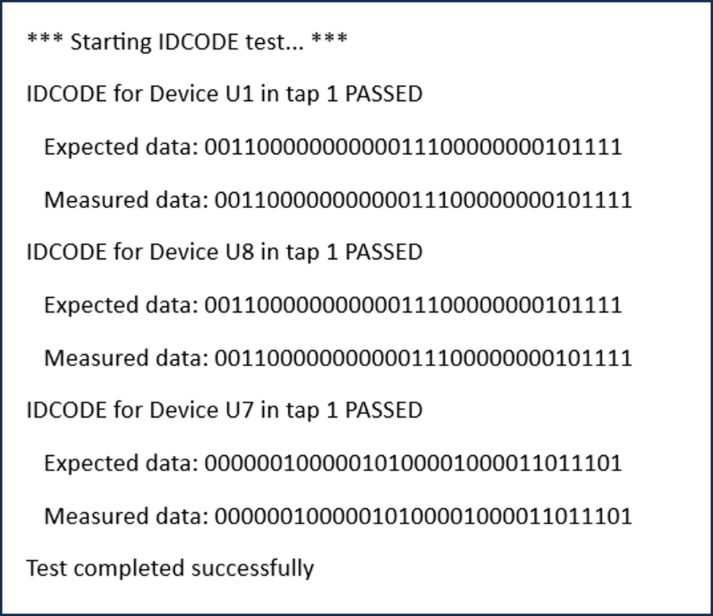
The IDCODES for the Boundary Scan devices match (Expected Data and Measured Data). The Expected data is read from the BSDL. The Measured data is received by ScanWorks once the option has been implemented.
Take note of the order the data is presented. Expected and Measured Data for U1 is presented first and Expected and Measured data for U7 is presented last.
Referring to the ScanLite2 diagram, you’ll observe that U1 is the Boundary Scan device nearest TDO. As data is shifted out, the Boundary Scan device nearest TDO’s data is received back at ScanWorks first. U7 is closest to TDI so its data comes out of TDO and is received last.
Running the IDCODE option with the switch open.
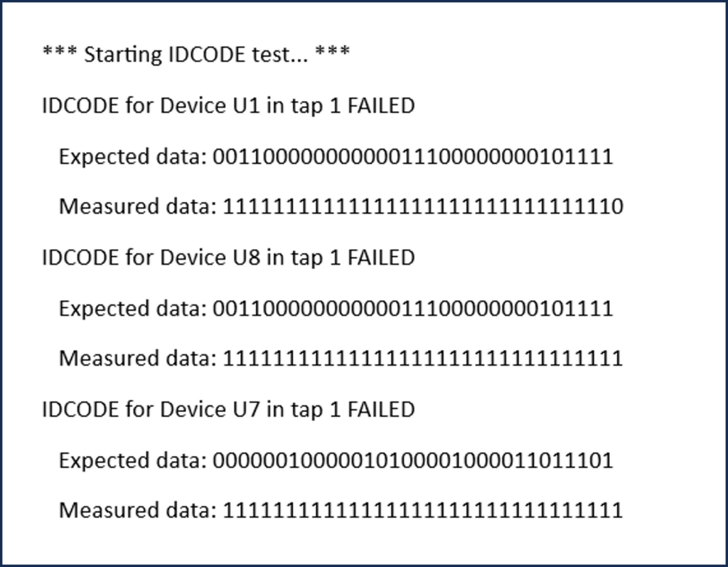
The screenshot above is from the log when SW5 is open.
In the last blog (Part 8), you’ll recall that we ran the DeviceID and Bypass DR Scan Only option test.
As a reminder, when a Boundary Scan device powers up or is reset, either the IDCODE (optional register) or the BYPASS register (mandatory register) will be automatically configured between TDI and TDO within the Boundary Scan device. If the IDCODE register exists, it will be configured between TDI and TDO. The DeviceID and Bypass DR Scan Only option scans out the contents of the register configured between TDI and TDO. The Boundary Scan devices on the ScanLite2 all contain an IDCODE register so the contents of the 32-bit IDCODE register are shifted out.
The IDCODE option performs differently than the DeviceID and Bypass DR Scan Only.
The IDCODE option goes through the CAPTURE, SHIFT, and UPDATE states, but ScanWorks shifts in the instruction OPCODE to each Boundary Scan device to configure the IDCODE register between TDI and TDO.
Take note that with SW5 open, U1 is now failing. When we ran the DeviceID and Bypass DR Scan Only, the IDCODE passed even though the rest of the Boundary Scan devices failed with SW5 open.
The difference here is that the instruction for IDCODE is shifted through the Scan Path to the U1. With the break between U8 and U1, the IDCODE is not received at U1. An all 1’s pattern is shifted into U1 (due to the internal pull up resistor at TDI).
An all 1’s pattern is the OPCODE for the BYPASS instruction.
The all 1’s OPCODE is mandatory by the IEEE 1149.1 standard.
So instead of U1 being placed in IDCODE it is really in BYPASS, and the contents of the BYPASS register are shifted out. You can see that logic 0 is at the beginning of the Measured data stream. The data streams are read from right to left. Afterward, there are 1’s (31 to be exact).
Since the IDCODE option is selected to be run, the TCK will cycle through 96 times, enough cycles to shift out the contents of 3, 32-bit IDCODE registers.
The next option is the Boundary Scan Length.
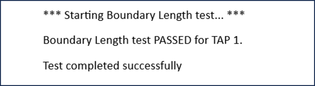
When we close the SW5 switch, the log below is produced. Nothing exciting to see except that the option passes.
Next, we’ll open the switch and run the Boundary Scan Length option.
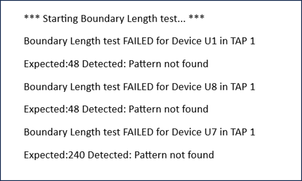
This log is with the SW5 open, and the Boundary Scan Length option is run again.
There is a message stating that a pattern is not found for each Boundary Scan device. The Expected data pattern of 48 bits for Boundary Scan devices U1 and U8 are not found and a data pattern of 240 bit for Boundary Scan device U7 is not found.
Let’s delve into the meaning of this.
This Boundary Scan Length option captures and shifts out the contents of the Boundary Scan register for each Boundary Scan device and sends this data back to ScanWorks via TDO.
Since the value of each register is indeterminate (either logic 0 or logic 1), the Measured data and the Expected data cannot be compared reliably. There will be a total of 336 bits initially shifted out of the Scan Path TDO back to ScanWorks.
The Boundary Scan Length option test really starts after bit 336. ScanWorks sends in a known data pattern stream into the Scan Path that is shifted through the Boundary Scan cells in the Boundary Scan devices and should come out of TDO.
Since ScanWorks has determined and shifted this data pattern stream into the Scan Path (Expected), the Measured (received) values can be compared to the Expected values. The determined data stream is a very long pattern and is known as the Test Stimulus. The test stimulus is based on an internal algorithm that considers the number of Boundary Scan devices on a board and the size of each Boundary Scan Register. This algorithm generates hundreds of bits that are shifted through the Scan Path. As the bits are shifted from Boundary Scan Cell to Boundary Scan Cell, the CAPTURE, SHIFT, and UPDATE functions are being exercised and the connections between the Boundary Scan Cells are validated.
The third option is USERCODE.
Run the USERCODE option with SW5 closed then opened:
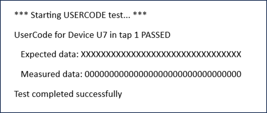
With SW5 closed, we see a message stating USERCODE test passed. USERCODE is an identification for programmable parts. The programmable parts on ScanLite2 have not been configured. Configuring programmable parts can change the Boundary Scan Cell structure.
I discussed the pros and cons of testing with configured Boundary Scan devices as part of my webinar “Guidelines for Board Design for Test (DFT) based on Boundary Scan Webinar #2”.
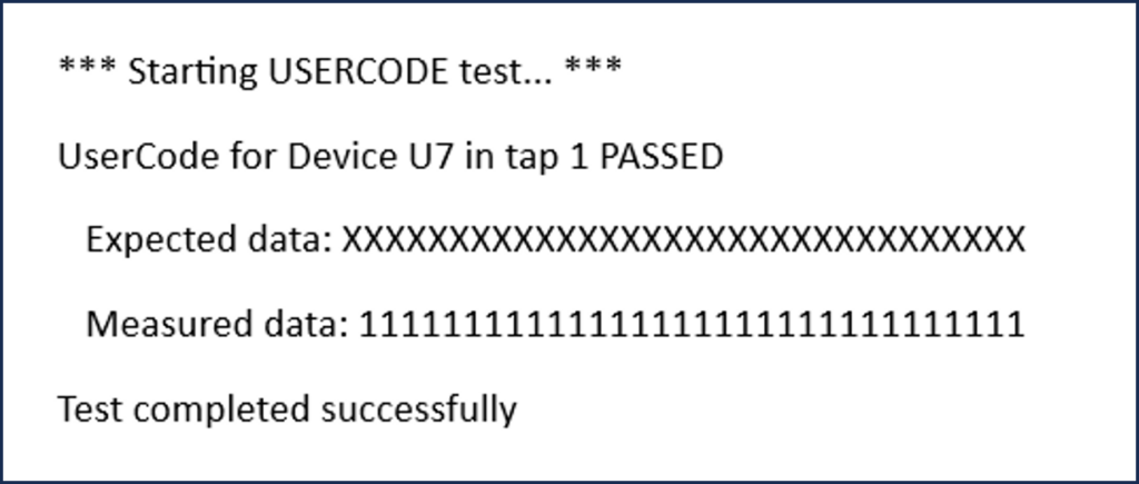
We see the measured data either be 0 or 1. The measured data is 0 when SW5 is closed and 1 when SW5 is open since there is no Expected data. The Expected data and Measured data are different. The Expected data is all X’s, this is a “don’t care” in ScanWorks.

For completeness, I ran the TRST test. Not very interesting results. The Boundary Scan devices on our board do not have the TRST pin so this test will not be performed.
In the upcoming blog, we’ll examine the debug capabilities of the Scan Path Verify action.