
In addition to running the options of the Scan Path Verify action from the Define a Scan Path Action, the options can also be run from a debugger dialog.
The options available from the debugger are limited to 3 types. These 3 types are sufficient to gain more insight and diagnose issues with the Scan Path.
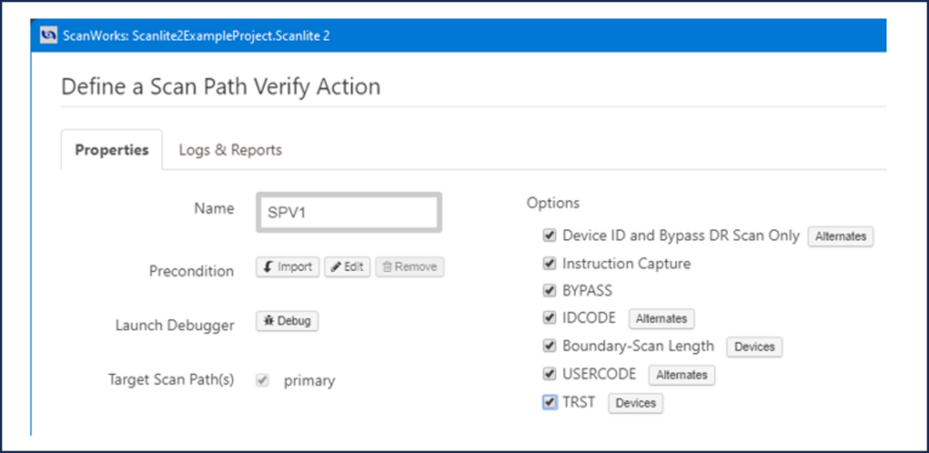
Start the Debugger Dialog.
Select Launch Debugger from the Define a Scan Path Verify Action dialog.
There are 3 views in the debugger:
-
- Instruction Capture
- BYPASS
- Boundary-Scan Length
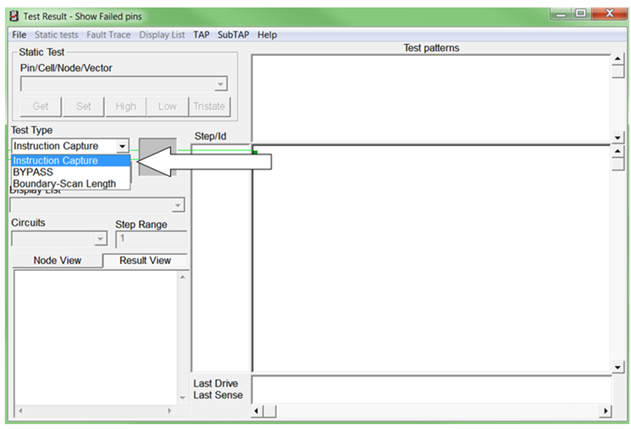
The test types available are a subset of the options available from the Define a Scan Path Verity action. However, these 3 options are sufficient to diagnose structural problems on the boards, structural problems in the devices, and register issues.
Let’s look at Instruction Capture.
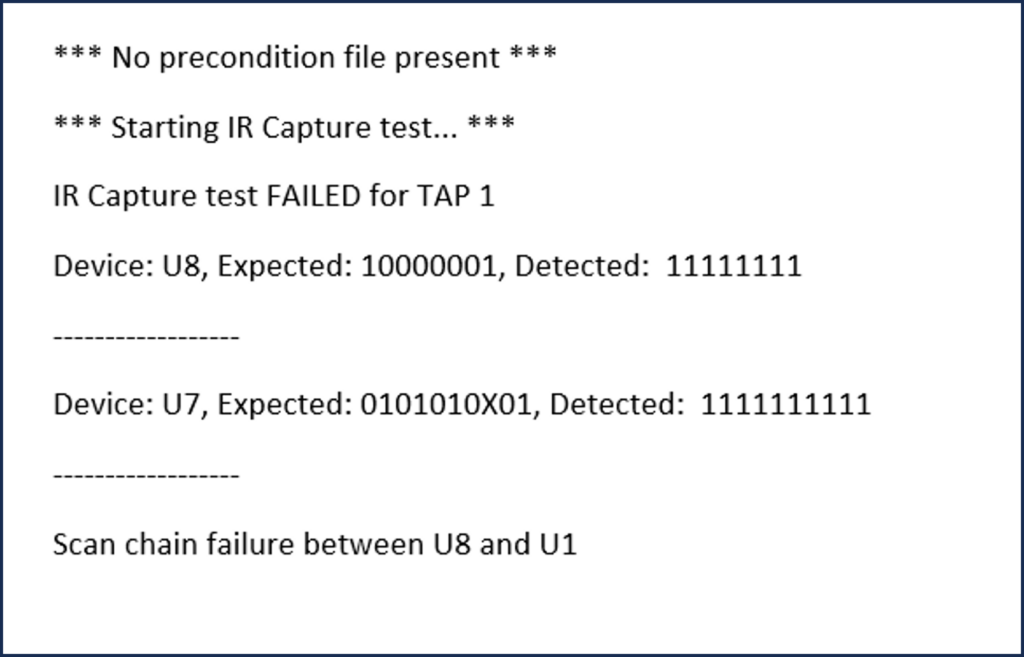
As a reminder, Instruction Capture checks the Instruction Register Capture Value for all Boundary Scan devices in the Scan Path using IR scans with the BYPASS instruction.
The Instruction Capture option verifies that the Instruction Register for each device is functioning correctly. The Instruction Capture Value is hard-wired within the Boundary Scan device on its parallel inputs.
During the CAPTURE state, the Capture Value is uploaded into the 1st rank of the Instruction Register then during the SHIFT state it is shifted out via TDO. The Capture Value is also listed in the BSDL file. When shifted out, the Expected Value from the BSDL is compared to the Detected Value.
I’ll create a fault by leaving the SW5 open and will run each of the test types so we can examine the logs and how they compare to the information presented in the debugger dialog.
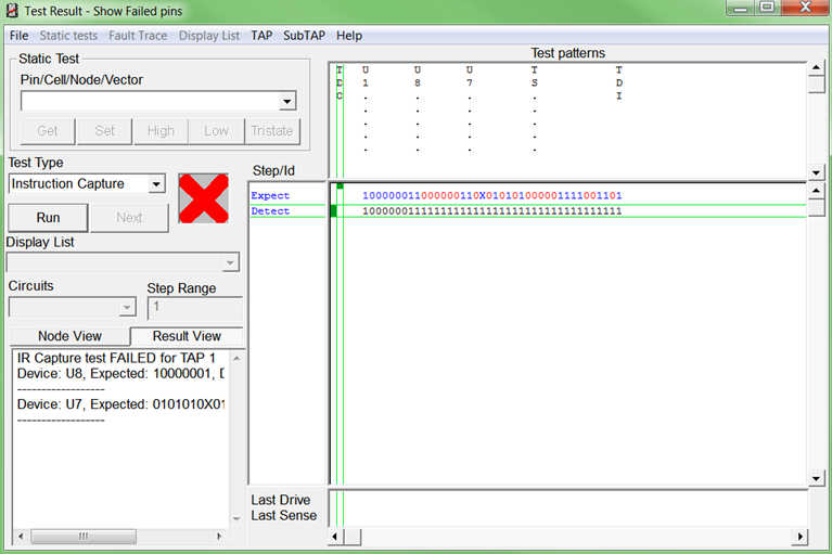
This view is from the debugger, also known as the ‘Test Result – Show Failed Pins’ dialog. I’ve run the Instruction Capture and as you see, the Instruction Capture fails as indicated by the red X.
There is also a message in the Node View. This is the same information as presented in the log file. The ‘Test Result – Show Failed Pins’ dialog shows us the bits that were expected and detected and how they are compared.
Here is the legend for the colors:
- Blue=Compare
- Red=Mis-compare
- Black=Detected values
The data stream is read left to right, starting at the vertical TDO. As a reminder, the order in which the data comes out of the Scan Path is U1, U8 and U7 (the starting point is always the device closest to TDO). The vertical boundaries indicate where the Instruction Capture value begins and ends for each Boundary Scan device.
Starting from TDO, the Instruction Capture Value for U1 compares to the detected data. At U8 and U7 there are red bits. These bits are mis-compared to the detected values. This continues up to TS. TS stands for Test Stimulus. (More about TS later.)
As you can see, the Instruction Capture Values for U8, U7, and TS all mis-compare. This indicates that there is a break in the Scan Path between U1 and U8.
Next up is BYPASS.
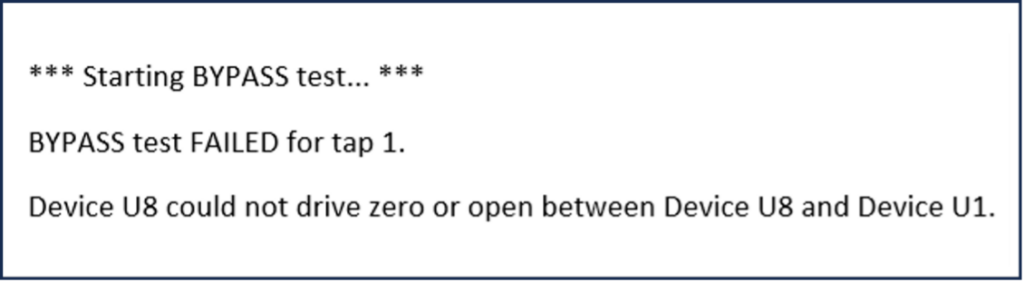
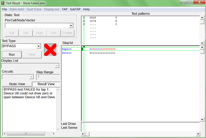
With SW5 open, BYPASS fails as indicated with a red X. There is also a message in the Node View.
We also see the bits that compare and bits that mis-compare. There is a blue 0 for U1 which compares, but there are red 0s and 1s afterward. The TS bits are red as well. This stream of red bits indicates that there is a break in the Scan Path between U8 and U1.
Let’s look at the Boundary Scan Length option and discuss the TS or Test Stimulus.
When running some of the SPV options, the normal shifting process is extended to add additional Test Stimulus (TS) bits to the end of the data stream, immediately following the shifted-out bits of the captured data. TS is shifted in through TDI and shifted out through TDO.
The purpose of the TS is to further verify TAP controller operation, further verify the Scan Path and test bus, and check the length and integrity of the Boundary-Scannable registers.
The TAP controllers of the Boundary Scan devices are held in the SHIFT-IR or SHIFT-DR states long enough to shift out all captured and TS data. The TS pattern is a binary count pattern.
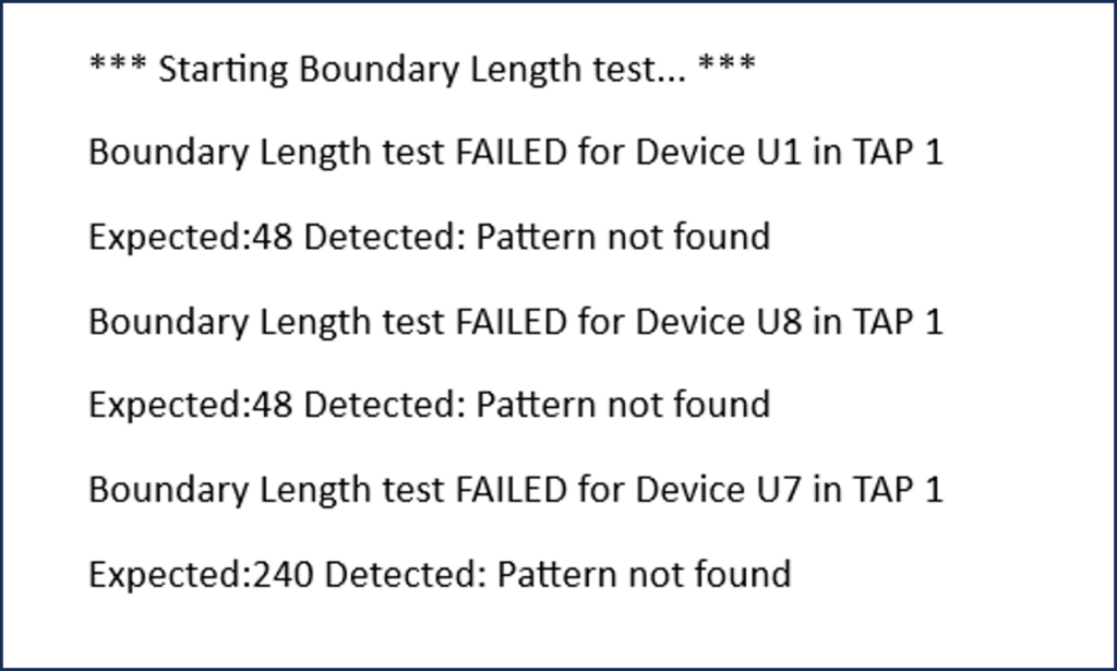
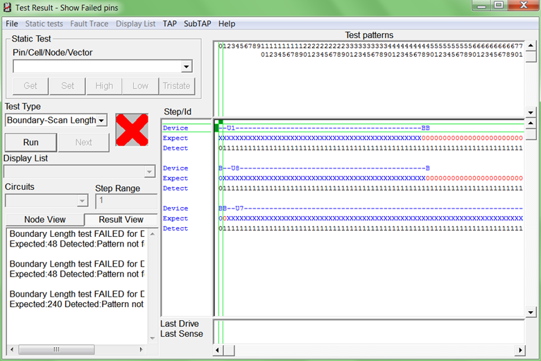
This Boundary Scan Length option captures and shifts out the contents of the Boundary Scan register for each Boundary Scan device and sends this data back to ScanWorks via TDO.
Since the value of each register is indeterminate (either logic 0 or logic 1), the Measured data and the Expected data cannot be compared, thus you see blue Xs in the Expected row.
For this test, with the Boundary Scan devices on ScanLite2, there are 336 bits (the entire Boundary Scan register length of all 3 devices added together) initially captured and shifted out of the Scan Path TDO back to ScanWorks.
The Boundary Scan Length option test, in essence, starts after bit 336 bit.
ScanWorks sends in a known data pattern stream (a TS) into the Scan Path that is shifted through the Boundary Scan cells in the Boundary Scan devices and should come out of TDO.
Since ScanWorks has determined and shifted this known data pattern stream into the Scan Path, Expected, and Measured values can be compared to determine if the correct data stream pattern was received. ScanWorks tests the Boundary Scan Register of each device in order from the last device in the Scan Path to the first device in Scan Path (U1, U7, U8).
Scan Path Verify summarized.
The Scan Path Verify action detects physical faults associated with the Boundary Scan infrastructure, such as the test bus and the TAP controllers.
The action also verifies that the physical Scan Path of the unit being tested matches the Scan Path described in the original BSDL descriptions of devices and the Scan Path description for the unit being tested.
In addition to testing the infrastructure, the Scan Path Verify tests help to validate that the Scan Path description described when using ScanWorks’ Design Wizard matches the actual Scan Path on the board. If the Scan Path Verify tests fail, it may not always be due to a physical fault on the board. For example, if the order of devices in the chain was incorrectly described, or if an outdated version of the device’s release level appears in the BSDL file (reflected in an incorrect IDCODE value), the tests could fail.
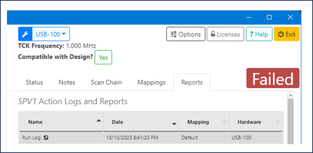
ScanWorks reports any faults detected and provides the location of the fault. A Scan Path Verify action automatically runs a reset action before and after the action is applied. This is to ensure that the hardware begins and ends in a safe state.
Changing the order of the Scan Path is easily accomplished using ScanWorks’ Design Wizard.
Stay tuned for Part 11 of “Everything You Need to Know About ScanWorks Interconnect.”