
Before we can test our device-to-device interconnects with an Interconnect action, we need to complete the Describe Design step. The time has come to work with a netlist!
In previous blog posts, we’ve discussed importing the BSDLs for ScanLite2, building them to check for syntax and semantics errors, and designing the Scan Path using ScanWorks’ Design Wizard. This is considered Part 1 of the Describe Design step in the ScanWorks Project Design process that we teach during ASSET’s 4-day Boundary Scan Workshop.
As part of the project design process, we’ve also implemented the step “Test Boundary Scan Path Operation” by verifying the BYPASS, IDCODE, Instruction, and Boundary Scan registers and the TAP controller within each Boundary Scan device on our ScanLite2 are operational by running a Scan Path Verify action.
Completing the Describe Design step.
In Part 2 of the Describe Design step, we’ll provide ScanWorks with information regarding the types of devices on ScanLite2 and how these devices, Boundary Scan, and non-Boundary Scan devices, are connected via a netlist. We’ll also identify power and ground nets and assign cluster models to the non-Boundary Scan devices.
| Describe Design Steps | |
| Part 1 | Part 2 |
| a. Import BSDLs | d. Import and translate a netlist into ScanWorks format |
| b. Build BSLDs to check for syntax and semantics | e. Add power and grounds to the design description |
| c. Design Scan Path using ScanWorks Design Wizard | f. Specify cluster, dummy, and resistor models |
Import and Translate a Netlist into ScanWorks Format
A netlist is a file format that describes the components, connectivity, and optionally, the placement and routing of a printed circuit board.
There is a long list of EDA tools used by electronic board designers to create board schematics, arrange device layout on the PCB, and for netlist generation. Some EDA manufacturers are Cadence, Altium, Mentor, and OrCAD.
Each EDA tool can have a unique netlist format output. ScanWorks accepts a wide variety of netlist formats produced by EDA manufacturers. Netlist formats such as Allegro, Mentor Neutral, and PST-Cadence, are examples of outputs from EDA tools used by board designers. These formats can be imported directly into ScanWorks for translation into the ScanWorks format.
Based on the EDA tool used, the netlist output could consist of several files.
For example, if the Allegro netlist format is used, only the .net file is required by ScanWorks for netlist translation. However, to translate an OrCAD netlist, the Chip, Comps, and Nets files are required by ScanWorks for netlist translation.
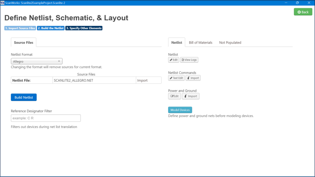
Using the Netlist Format dropdown to select the netlist format for translation, the ScanWorks UI reconfigures and allows the user to input the correct file type(s). When Build Netlist is selected, ScanWorks translates the format. This work is done at the Define Netlist, Schematic, and Layout UI.
Some netlist formats are not directly translatable by ScanWorks. In this case, ScanWorks, via a licensed add-on product named Creo View, can convert those formats into a standard Electronic Design Automation (*.eda) file. A .eda file can then be imported into ScanWorks and a netlist extracted from this data.
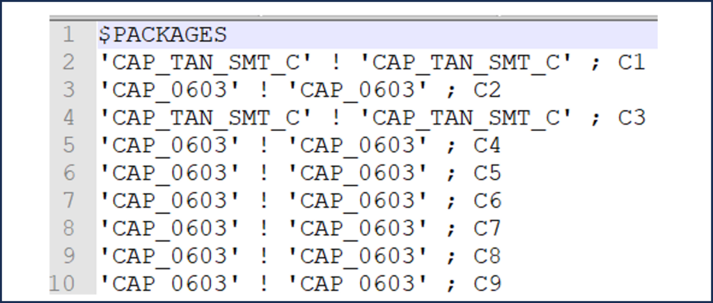
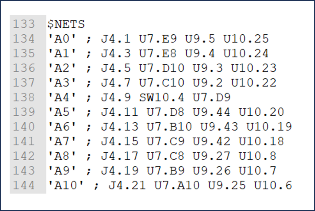
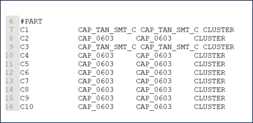
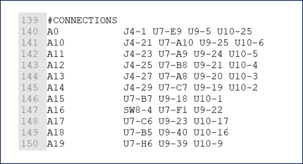
The netlist for ScanLite2 is in the Allegro format We’ll import and translate the Allegro netlist into the ScanWorks format. See snippets of the original Allegro netlist and ScanWorks translated netlist below.
Add Power and Grounds to a Design Description
Once the netlist has been built successfully, the Power and Ground edit button becomes active. We can begin to define power and ground nets on ScanLite2.
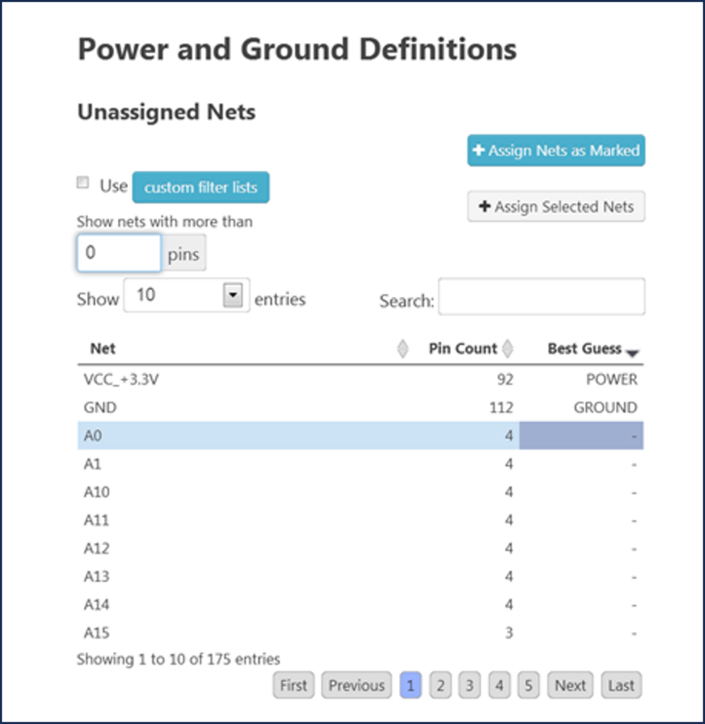
The dialog we use to define power and ground nets is shown below. When this dialog is opened, ScanWorks reads the netlist to determine the power and ground nets on the board based on the net name. ScanWorks searches the netlist for keywords such as “POWER”, “PWR” and “VDC” for power nets. For ground nets, ScanWorks searches the netlist for keywords such as “GND”, “GROUND” and “VSS”.
Power has two designations, Power and Weak Power. Power identifies voltage nets associated with Boundary Scan circuits. Weak Power identifies voltage nets where the logic level may not be captured reliably as valid logic high. Ground identifies ground nets associated with Boundary Scan circuits.
ScanWorks will list all the nets on the board with an indication of “Best Guess”, which is a list of nets that it has determined to be power and ground nets in the design. The list is determined based on a text search (again using Power, PWR, VDC, Ground, GND, VSS, etc.). ScanWorks also looks at the net size.
Power and ground nets typically have the highest number of pins connected to them. If ScanWorks identifies power and ground nets that should not be marked as such, they can easily be unmarked. The search criteria are editable to include other power and ground designations.
- If we agree with ScanWorks’ best guess as to the appropriate power and ground nets on the ScanLite2, we only need to select Assign nets as Marked to add the power and ground nets to the appropriate field of the dialog box.
- If there are other nets that should be marked as power or ground that were not automatically identified, they can be assigned manually using the Assign Selected Nets.
We specify Power and Grounds in ScanWorks for several reasons.
ScanWorks strives to create safe tests so identifying power and ground nets prevents ScanWorks from driving nets that it shouldn’t. ScanWorks also uses power and ground net information to test for the presence of pullup or pulldown resistors. The board may contain resistors connected to Boundary Scan pins that are pulled up or pulled down via a 10K ohm resistor (for example).
By specifying power and ground nets, ScanWorks will be able to determine from the power and ground nets whether the resistors are pull-ups, pull-downs, or series resistors. Defining power and grounds saves a great amount of time when working with resistors, because ScanWorks automatically does this classification. Defining the power and ground nets also allows the interconnect test vector generator to avoid driving a dangerous state out of a pin that’s tied directly to power or ground.
Now keep in mind we only need to identify power and ground nets that apply to Boundary Scan circuitry. A board may have Analog circuity and power. Analog power and ground nets do not need to be defined.
Specify Cluster, Dummy, and Resistor Models
The final step of the Describe Design process is to specify cluster, dummy, and resistor models.
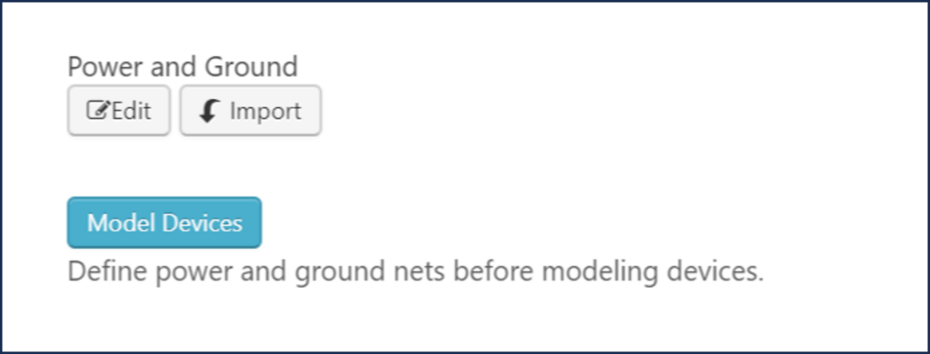
By specifying these items in the netlist, this information becomes global, and will be used by subsequent actions requiring a netlist such as Interconnect, Memory Access Verify, Flash, and I2C. This dialog is not available until the Power and Grounds have been assigned.
To access the Model Devices browser, select the Model Devices button.
I’ll wrap up here and will continue with how to model devices in the next blog. Modeling is a lengthy topic, so I believe it deserves a blog of its own.
Modeling devices are an important part of the test coverage ScanWorks Interconnect provides. The Interconnect test action is used to verify that the PCB is free of assembly defects such as shorts and opens. Without proper modeling, test coverage will be extremely low. Understanding modeling ensures the best test coverage possible with Boundary Scan.
Stay tuned for Part 12 of “Everything You Need to Know About ScanWorks Interconnect”, where we’ll continue to discuss netlists.