ScanWorks strives to create safe tests, meaning that it will not drive a net to a logic-1 or logic-0 unless it knows it is safe to do so. Driving nets to incorrect logic levels can cause bus conflicts and could even damage devices (ex. back-driving an output pin as though it was an input).
We have reached the last step in the Describe Design process. It’s time to use the Device Browser to specify cluster, dummy, and resistor models for the non-Boundary Scan devices on our board; in this case the ScanLite2 board.
(To learn about importing and translating a Netlist, check out Part 11 of this blog series.)
Modeling non-Boundary Scan Devices
Without modeling the non-Boundary Scan devices, the shorts and opens coverage reported by ScanWorks when running an Interconnect test action would not be maximized.
To determine what nets are safe to drive and at what level, ScanWorks’ Interconnect uses models of non-Boundary-Scan devices that describe their I/O characteristics. Using the I/O characteristics, and how the device is connected to other devices via the netlist, ScanWorks determines which nets are safe to drive and at what logic levels to drive them.
The Device Browser is invoked by selecting the Model Devices button on the Netlist, Schematics & Layout UI. You must import and translate a netlist along with specifying the power and ground nets for your design before assigning cluster, dummy, and resistor device types using the Device Browser.
Cluster Models (Resistors, Cluster, Dummy)
Cluster models are ASCII files that are used to improve fault coverage during Interconnect testing. ScanWorks uses cluster models to trace through non-Boundary-Scan devices to determine access to other Boundary-Scan devices. Cluster models describe the behavior of a non-Boundary-Scan device that can be controlled using Boundary-Scan devices.
Resistors
Looking at the circuit below, there are two Boundary Scan devices with a net connecting them. Since ScanWorks has knowledge of how the Boundary Scan devices operate (via the BSDL files), this net can be driven safely, in the absence of the resistor. However, when a series resistor is placed on the net, and if it is not modeled as a resistor in ScanWorks, ScanWorks will not drive this net, thus losing Boundary Scan coverage on this net. The resistor model informs ScanWorks that it is safe to drive this net.
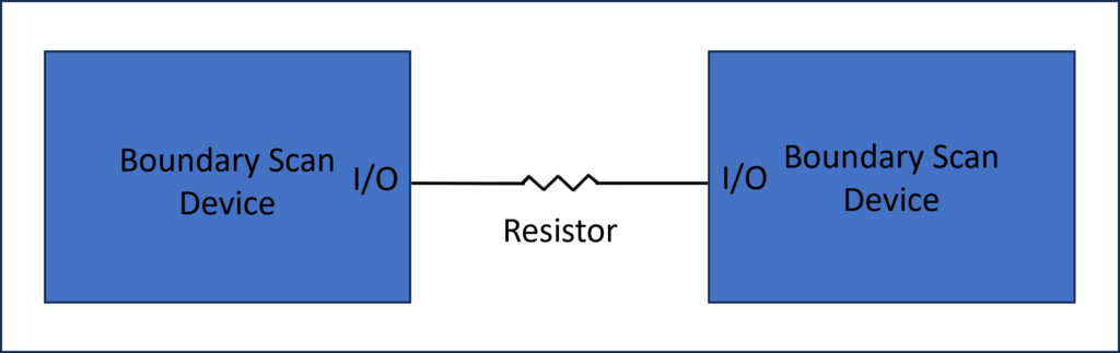
The model for the resistor is simple and uses the keyword RESIST.

Cluster
Cluster models use simple Boolean expressions to define simple functions and behaviors of a non-Boundary Scan device. Behaviors are called PART sections in the cluster model. Looking at the circuit below, there are two Boundary Scan devices with a 74ACT244 buffer between them.
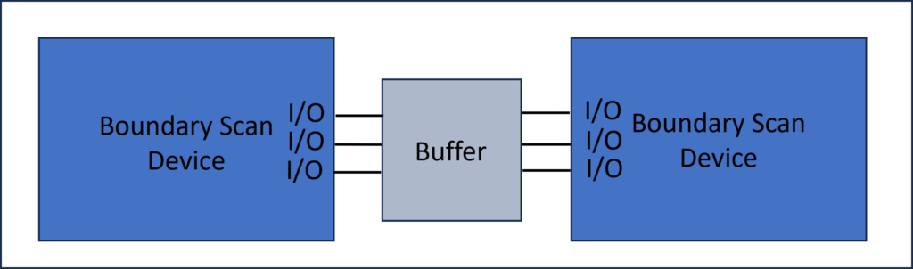
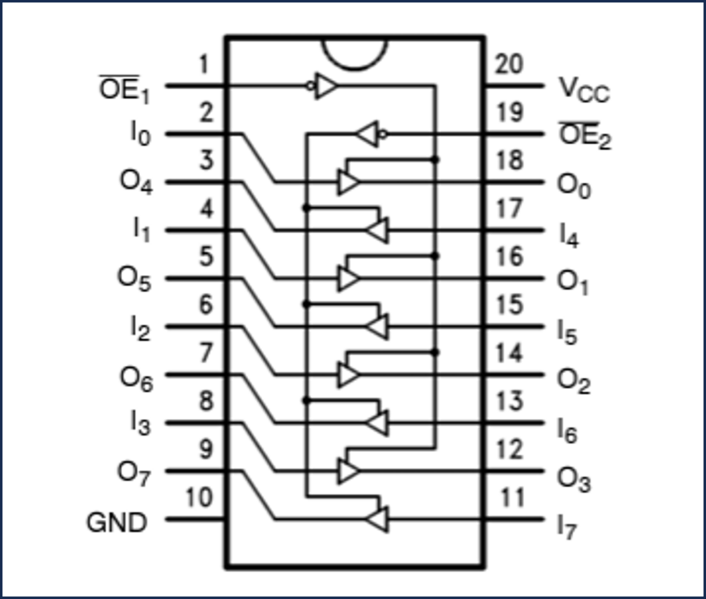
The buffer can implement several different behaviors or PARTS. One behavior of the device is that the entire device can be turned “on” (all buffer ports utilized) or the entire device can be turned “off” (all buffer ports not utilized). Both are based on the OE1 and OE2 enable pins asserted or not.
Another behavior of this device is that one section of the buffer could be “on” while the other section of the buffer could be “off,” or vice versa (again, based on the assertion of OE1 and OE2). The behaviors of this device are based on the truth table from the data sheet.
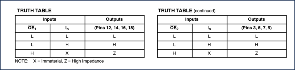
ASSET cluster models are written based on the truth table and use simple keywords such as DRIVE and EQUAL. Here is a snippet of the cluster model for the 74ACT244 buffer from the ASSET Model Library.
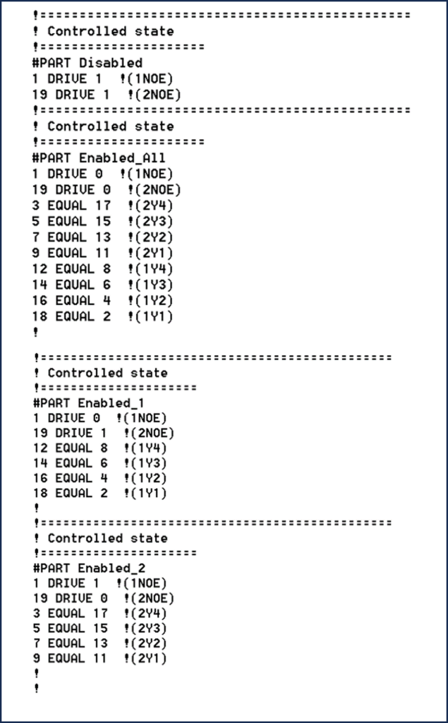
ScanWorks analyzes the cluster model along with the netlist to determine how the device is connected on the board. Utilizing this information, ScanWorks generates safe patterns to test the device and the Boundary Scan devices connected to it. The test patterns are generated by ASSETs Test Pattern Generator. During ASSET’s 4-day Workshop, we discuss the topic of cluster models and how they increase test coverage.
Dummy
Regarding dummy devices, there may be some devices on the board that are remote from the Boundary Scan nets, meaning that the devices do not connect to a Boundary Scan device – either directly or indirectly through another non-Boundary Scan device. In that case, the device could be defined as a dummy device, meaning that it is a don’t-care device. This will save the effort of acquiring or creating a cluster model for the device. This is a perfectly fine way of treating the device since it will never be part of an interconnect test. The dummy model is most often assigned to test points, LEDs, oscillators, etc. Again, these are devices that you know can be driven without damaging the device.
Regarding capacitors, most capacitors on a board are power bypass filter capacitors and can be listed as dummy devices. The device type Capacitor can be used. When using the device type Capacitor, ScanWorks will resolve whether the capacitor is a bypass capacitor or a serial capacitor on I/O signals between Boundary Scan devices. This is an AC coupled net and is typical on high-speed nets that employ Boundary Scan devices capable of implementing the 1149.6 standard.
Regarding protected devices, there may be cases where it might be prudent to leave a device protected, even though the goal is to eliminate as many protected devices as possible. An example of a case where a device may have to be left protected is a digital to analog converter. The board may be designed such that an unconstrained set of stimuli on the DAC’s digital inputs could cause damaging conditions on the analog side of the converter, such as excessive voltage or current levels in the analog circuitry fed by the DAC. In that case, it might be wise to either leave the DAC as a protected device or to use constraints on the Boundary Scan device(s) driving the DAC, so that any illegal digital input combinations cannot be generated.
ASSET’s Cluster Model Library
You may wonder, since there are thousands of non-Boundary Scan parts on the market (ex. buffers, switches, memory devices, flash devices, etc.), “Do I have to create cluster models for non-Boundary Scan devices on my board?” The answer is “no.”
ASSET provides a library of cluster models for thousands of common devices to customers with an active maintenance agreement. The ASSET Model Library can be accessed directly from ScanWorks during project development so this does not interrupt the project development flow. The cluster models can be used as is or used as a template for beginning a new cluster model.
How Do You Assign Cluster Models Using the Model Devices?
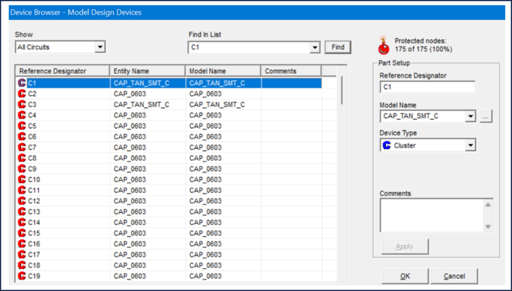
Let us tour the Device Browser, then look at the mechanics of how to assign non-Boundary Scan models using the Device Browser.
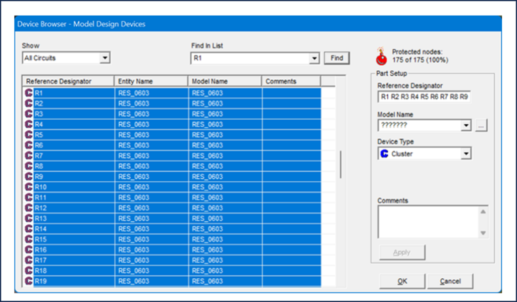
Once the Device Browser is invoked, you will notice that initially, all devices have a red C next to them. The red C indicates that the device is protected, meaning that it will not be actively driven during an Interconnect test.
Our objective from this point on will be to eliminate the red C’s, by mapping each device to a dummy, resistor, or cluster model. As this is done, the number of Protected Nodes decreases.
Let’s tour the Device Browser:
| Device Browser UI | |
| Show | Allows you to select what is shown in the device specification section of the dialog. Choices include: All Circuits, Capacitors, Cluster Circuits, Hidden Circuits, and Resistors. |
| Find in List | Shows all values that have been selected in the Device Browser in this session. < and > allow you to review the values selected. |
| Protected Nodes | Read only field that shows the number of nodes for this design description, and how many of those nodes are protected. |
| Reference Designator | Read only. Shows reference designator for device highlighted in device specification section. If multiple reference designators are selected in the device specification section, this field shows question marks. |
| Model Name | Shows current cluster model name for device highlighted in devices specification section. If multiple reference designators are selected in the device specification section, this field shows question marks. |
| Device Type | Allows you to specify the type of device for the reference designator shown in this section. Values available are: Cluster, Protect, Dummy, Resistor, and Capacitor. |
| Comments | Allows you to add text comments regarding device specifications for this interconnect action. |
| Apply | Applies changes made in the Part Setup section. If specifying multiple device types, select Apply after each specification. |
The Mechanics of Assigning Cluster Models
At first glance, you may think this process of assigning cluster models will take a long time, however, it can all be done quickly. In terms of resistors, using the standard Windows Select All feature (Ctrl-Shift) we can find all the resistors, and then assign the resistor model all at once.
Steps to Assign Resistors
- Select all resistors (can use Ctrl-Shift to select all)
- Select device type (resistor)
- Apply
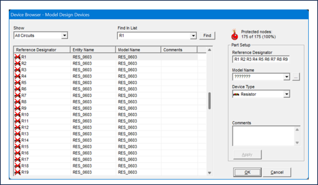
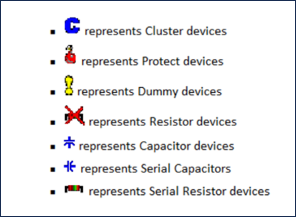
When we assign the resistor model, each resistor is represented with a resistor symbol with a red X, meaning it has not been classified. However, each resistor will be categorized by ScanWorks when an Interconnect action is built according to the graphic below.
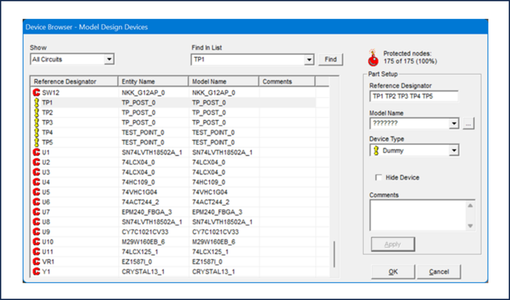
Steps to Assign Dummy
- Select all devices to Dummy (can use Ctrl-Shift to select all)
- Select device type (Dummy)
- Apply
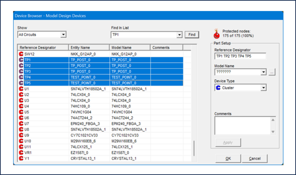
Steps to Assign Cluster
- Select non-Boundary Scan devices (collectively or individually)
- Select the appropriate Cluster model (may need to import from ASSET Model Library)
- Apply
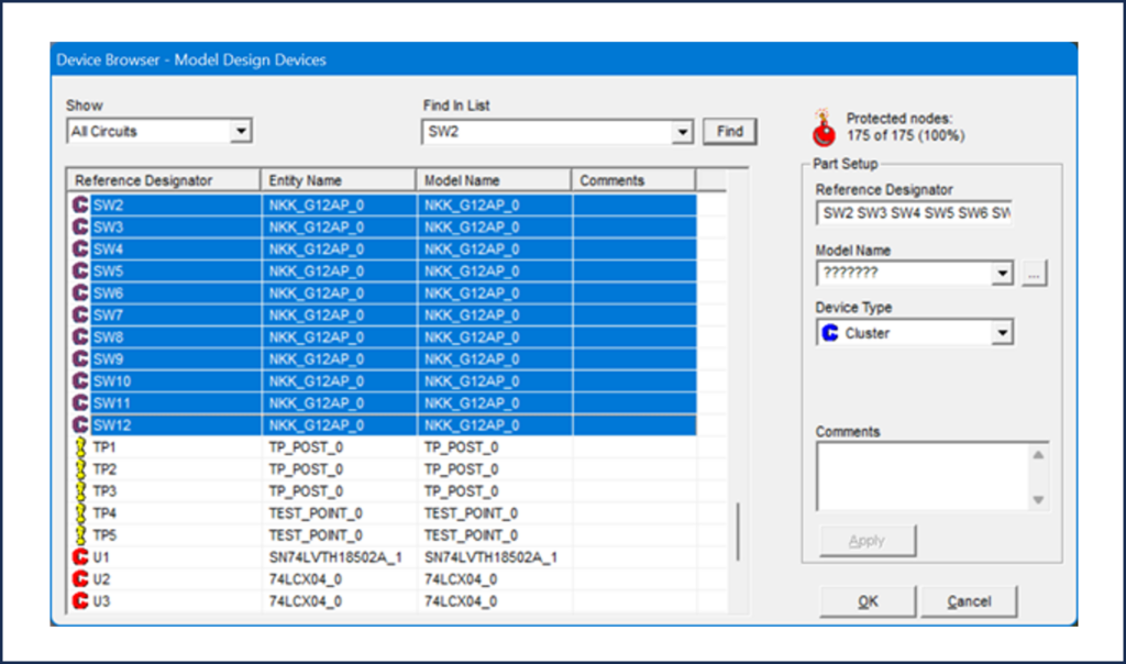
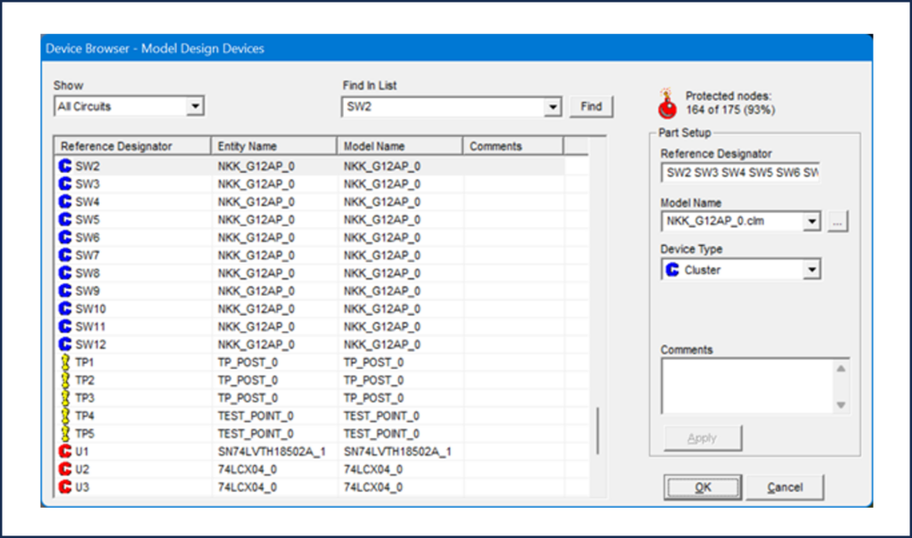
Now for the cluster example, I have selected the toggle switches on the ScanLite2 board to apply the model to.
ScanLite2 has several other non-Boundary Scan devices on it. For each remaining cluster device, ASSET has created a model that can easily be downloaded from our library and applied.
| ScanLite2 Cluster Devices | |
| Ref Des/Part Number | Device |
| SW1 | Dip Switch |
| SW2 – SW12 | Toggle Switch |
| U2 & U3 / 74LCX04 | Low Voltage Hex Inverter |
| U4 / 74HC109 | Dual JK Flip Flop |
| U5 / 74VHC1G04 | Inverter |
| U6 / 74ACT244 | Octal Buffer |
| U9 / CY7C1021CV33 | 1-Mbit (64K x 16) Static RAM |
| U10 / M29W160EB | 16 Mbit (1Mb x16, Boot Block) 3V Supply Flash Memory |
| U11 / 74LCX125 | Low Voltage Quad Buffer |
Your boards will have other non-Boundary Scan devices on them as well.
Once a cluster model has been downloaded from the ASSET Model Library, it is available for use in your next project.
Modeling is a crucial step that must be taken before building an Interconnect test to ensure maximum test coverage. There is an advanced function within ScanWorks called auto matching that reduces the time spent modeling devices.
Together with Part 11, this blog concludes our exploration into working with a netlist.
Stay tuned for my next blog in the “Everything You Need to Know About ScanWorks Interconnect” series.