
In my previous blog, I discussed about the mandatory and optional Boundary Scan Device instructions. Now, let’s dig a bit deeper into how the TAP works. The TAP provides 4 major operations within a boundary scan device. These operations are:
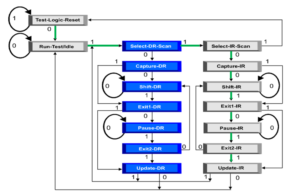
• Test-Logic-Reset: At the Test-Logic-Reset controller state, the test logic is disabled to allow for normal operation of the boundary scan device in its intended functional mode.
• Run Test/Idle: The Run-Test/Idle state controller state allows certain operations to occur depending on the current instruction.
• Select-DR-Scan: Begins a data-scan sequence.
• Select-IR-Scan: Begins an instruction-scan sequence.
Scans of data registers or the instruction register consist of 3 major states:
• Capture
• Shift
• Update
Capture allows registers to observe signals on their parallel inputs. Shift allows registers to pass data through a serial shift path. Update allows registers to transfer data from the shift path to its parallel output. The Capture, Shift, and Update states apply to all boundary scan registers. Each register and cell, no matter the type, can perform the Capture, Shift and Update operations. We’ll cover the various boundary scan cell types defined by the 1149.1 standard in future blogs as we continue our ScanWorks Interconnect journey.
Since every 1149.1 compliant register and boundary scan cell can perform the Capture, Shift, and Update operations, we will focus our attention on one register and examine how the Capture, Shift, and Update states are implemented. Once we have a clear understanding of how the Capture, Shift, and Update states are implemented on one register, we can apply this knowledge to the other registers. With this in mind, we’ll focus our attention on the instruction register.
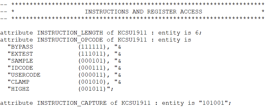
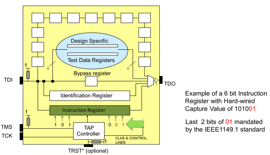
The instruction register holds the boundary scan instruction operation code (OPCODE), when decoded, will configure a specific data register between the TDI and TDO ports. The mandatory and optional instruction OPCODES found in boundary scan devices were discussed in the previous blog. As an example, I’ve included a snippet of a BSDL file, specifically the INSTRUCTION_LENGTH, INSTRUCTION_OPCODE, and INSTRUCTION_CAPTURE attribute sections for a boundary scan device with the name KCSU1911.
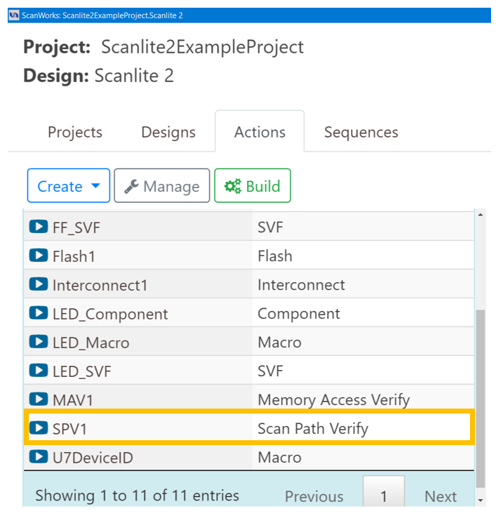
Let’s go through the mechanics of navigating the TAP. We’ll begin with the assumption that a boundary test action named Scan Path Verify (SPV) has been created in ScanWorks. Don’t worry, we’ll discuss how the SPV action is created and how it is used in a future blog. One thing I’ll mention is that a complete ScanWorks project and test actions can be created without a physical printed circuit board at hand. If the ScanWorks project designer has access to the printed circuit board design files such as the Boundary Scan Description Language (BSDL) files for the devices on the printed circuit board, the board netlist, the schematics, and bill of materials, a complete ScanWorks project can be created. Again, more to come on the ScanWorks project creation process later.
On the ScanWorks GUI, the end user will select the arrow icon to run the SPV1 action.
When the SPV action is run, ScanWorks will control the TMS and TCK signals which move the TAP of the boundary scan device through its various states. The interface between ScanWorks and the printed circuit board is the ScanWorks controller.
Step 1. Via the ScanWorks controller, TMS on the printed circuit board transitions:
- Logic-1 to logic-0 which transitions the TAP from Test-Logic-Reset to Run-Test/Idle
- Logic-0 to logic-1 which transitions the TAP from Run-Test/Idle to Select-DR-Scan
- TMS remains at logic-1 and transitions the TAP to Select-IR-Scan
- TMS transitions from Logic-1 to logic-0 and transitions the TAP to Capture-IR
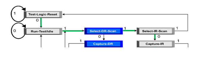
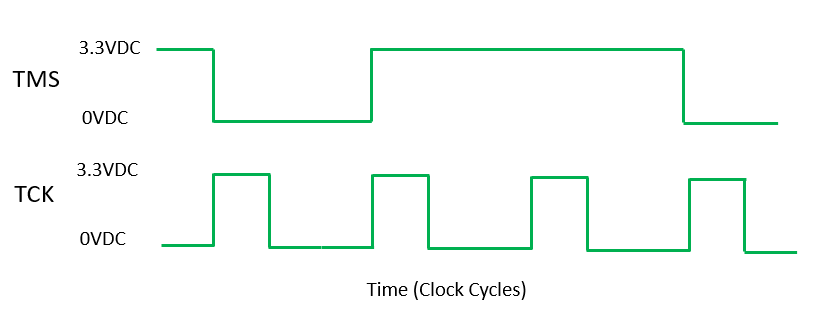
TMS transitions (highlighted in green) occur on the rising edge of TCK. If you view these transitions using an oscilloscope, the TMS and TCK transitions look like this:
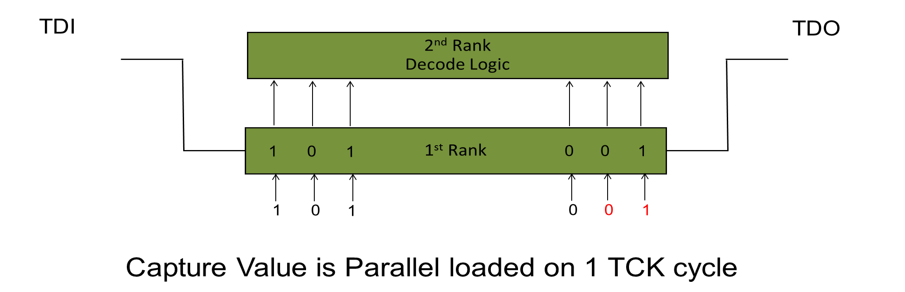
When the TAP enters the Capture-IR state, magic happens! The instruction register has a hard-wired value on its parallel inputs. This value is known as the capture value for the device. When the TAP enters the Capture-IR state, the hard-wired value is observed and parallel loaded into the first rank of the instruction register. For this example, the 6-bit capture value for device KCSU1911 is 101001. Each boundary scan device on a printed circuit board will have its own unique capture value, as determined by its manufacturer. The capture value is also listed in the BSDL for a boundary scan device. Per the 1149.1 standard, the last 2 bits of a boundary scan device’s capture value are mandated to be 01.
As stated, instruction registers scans consist of 3 states, Capture, Shift and Update. During Capture-IR, the capture value is observed and parallel loaded into the 1st rank of the instruction register.
Step 2. TMS remains at logic-0 for another TCK clock cycle, the TAP enters Shift-IR
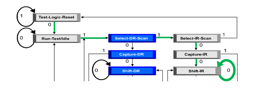
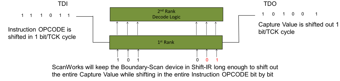
At Shift-IR more magic happens! The capture value that was loaded into the 1st rank of the instruction register is shifted, 1-bit at a time, out of the instruction register. In our example, it would take 6 TCK cycles to shift the capture value 101001 out of the instruction register. The capture value is shifted back to ScanWorks via the TDO port. Now you may ask “What is ScanWorks going to do with this capture value?” We’ll cover that later.
As the TAP is shifting the capture value out of the instruction register, ScanWorks, via TDI, is shifting into the instruction register an OPCODE. For the sake of this example, let’s assume the OPCODE that ScanWorks is shifting into the instruction register is EXTEST. Again, this process takes 6 TCK cycles, where the capture value is shifted out and the OPCODE for EXTEST replaces it in the instruction register. The TAP remains in the Shift-IR state long enough to accomplish this task (the “circle” with a logic-0).
![]()
Step 3. TMS transitions to Update-IR
TMS continues to transition to move the TAP though a few other states, namely EXIT1-IR, PAUSE-IR, and EXIT2-IR. Exit states are temporary hold states where a decision is made to either advance to the update states or pause states. The Pause state allows shifting of the instruction register and data register to be temporarily halted. There are several reasons why the TAP operations may need to exit or to be halted. We won’t delve further into the functions of these states at this time.
When the Update-IR state is reached, more magic happens! The capture value from the 1st rank is updated to the 2nd rank. The decode logic of the boundary scan device resides in the 2nd rank.
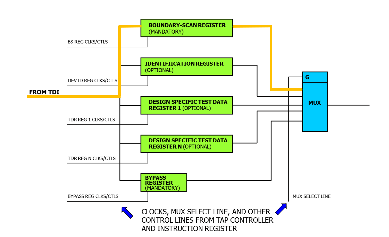
In our example, the OPCODE shifted into the instruction register is EXTEST. This means the register responsible for executing EXTEST commands, which is the boundary scan register, will be configured between the TDI and TDO ports when the Update-IR is reached (the gold line on the register mux diagram).
Once the instruction has taken place and the instruction has been loaded and the proper register has been configured between the TDI and TDO ports, the operations on the blue side of the TAP can take place.
![]()
Whew, that was a lot of operations, huh? But we are only halfway through the process. Just think, this process of observing and parallel loading the capture value, shifting it out while simultaneously receiving the instruction OPCODE, and updating the OPCODE to the decode logic happens every time an instruction is executed. During a sequence of boundary tests, this process can happen hundreds of times. Also, this process occurs across every boundary scan device at the same time. Just understanding this really makes you appreciate the power of boundary scan and the thought that was put into conceiving this test technology.
With the EXTEST instruction decoded, and the boundary scan register between the TDI and TDO ports the next operations will scan down the blue side of the TAP to execute the instruction on the data register. EXTEST is the test used to determine shorts and opens. The boundary scan cells responsible for executing these tests are able to implement capture shift and update as well.
In the next blog, we’ll cover what happens once an instruction is decoded, and a register has been configured between the TDI and TDO ports. We’ll also explore the operation of the most commonly used boundary cell, the BC_1.