The MSP430 is a mixed-signal microcontroller family from Texas Instruments. Built around a 16-bit CPU, the MSP430 is designed for low cost, low power consumption embedded applications. But, does it support boundary scan for board test purposes?
The MSP430 is a fairly ubiquitous chip, deployed in millions of systems worldwide. Available in a large variety of SKUs, it is ideally suited to numerous different applications, ranging from smoke detectors to heart rate monitors to circuit breakers, to name just a few.
The MSP430 family was designed by TI without 100% compliance to the IEEE 1149.1 (JTAG) specification. The JTAG interface on these devices is suitable for debugging, program development and flash programming only. From the JTAG (MSP430) – Texas Instruments Wiki:
However this JTAG interface is not 100% IEEE 1149.1 (JTAG) compatible. For example none of the MSP430 devices has Boundary Scan Cells. We only support the required command BYPASS, but don’t support the other required commands for example EXTEST and SAMPLE/PRELOAD.
Therefore there is no BSDL file for any MSP430 devices. In addition you can not put a MSP430 into a JTAG chain together with other devices.
For small systems, where perhaps structural test is skipped and the printed circuit board is only subjected to functional test during the manufacturing phase, this is not a major issue. But, for larger systems that may have physical access challenges that preclude a “bed-of-nails” test approach, this needs to be worked around.
In that vein, the last sentence from the Wiki excerpt above, “you can not put a MP430 into a JTAG chain together with other devices”, is perhaps overstated. From the TI User’s Guide, MSP430™ Programming With the JTAG Interface:
The JTAG pins are shared with port functions on all devices with a TEST pin. This includes the 5xx, 6xx, and FRxx families as well as certain device groups from the 2xx and 4xx families (see Table 1- 14). On these devices, a special entry sequence must be sent to enable 4-wire JTAG connection.
The MSP430 device must be the first device in the JTAG chain (because of clocking on TDI and JTAG fuse check sequence).
From the documentation, if it is desired to include the MSP430 device in the same chain as the other JTAG devices, it may be possible, but with at least these cautions:
- The MSP430 device must be first in the chain.
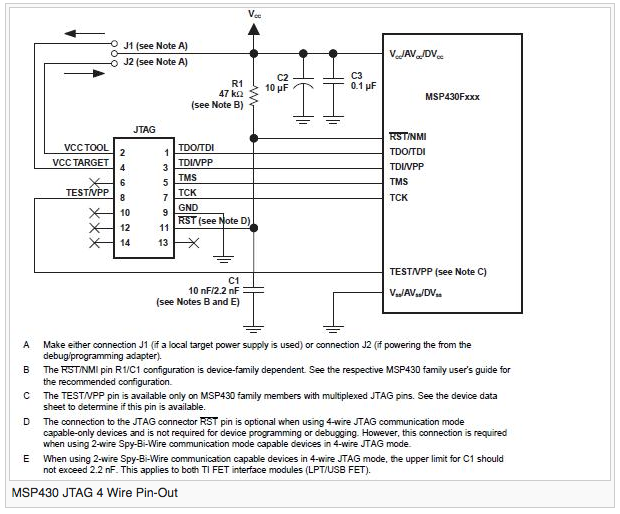
- There must be access to the TEST(SBWTCK) pin and to the RST(SBWTDIO) pin. See as an example the 4-wire JTAG diagram excerpt from the JTAG (MSP430) – Texas Instruments Wiki below.
- Practical experience recommends that TEST have an external (e.g. 4.7 kOhm) pulldown, since otherwise, unintentional rising signal edges (such as those induced when the JTAG connector is connected to the target device) can cause the test logic to enter an indeterminate state.
- It is strongly recommended to make provisions to readily rework the combined chain to break out the MSP430 and other JTAG devices into separate chains.
I would like to thank Adam Ley of ASSET InterTech for providing the inspiration and much of the technical content for this article.
For those who would like to know more, an excellent introduction to boundary scan is here: JTAG and Boundary Scan Tutorial (note: requires registration).


