
In addition to the BC_1 Boundary Scan cell type described in my previous blog, there are more Boundary Scan cell types that can be used to create a Boundary Scan Register and implement the IEEE 1149.1 operations within a Boundary Scan device.
The type(s) of Boundary Scan cell(s) implemented within a device are listed in the BSDL. Specifically, the attribute BOUNDARY_LENGTH tells us the number of Boundary Scan cells that comprise the Boundary Scan Register, and the attribute BOUNDARY_REGISTER tells us the type(s) of Boundary Scan Cells that comprise the Boundary Scan Register.
Basic Cell (BC)_0 through BC_7 are the standard Boundary Scan cell types commonly found in an IEEE 1149.1 compliant Boundary Scan device. You may ask the question, “Are there more Boundary Scan cells than BC_0 through BC_7?”
There are actually 100 BC cells defined in total. According to Ken Parker, author of the Boundary Scan Handbook Third Edition, “the 1149.1 Working Group reserved the names BC_0 through BC_99 to give the ability to define 100 standard cell designs, although it is very unlikely the Working Group will ever define more than a fraction of these.”
In addition to BC_0 to BC_7, there are other Boundary Scan cell types.
To this point in my blog series, we haven’t discussed devices that adhere to the IEEE 1149.6 standard. IEEE 1149.6 is the Standard for Boundary Scan Testing of Advanced Digital Networks.
IEEE 1149.6 is an extension of the IEEE 1149.1 standard, and it was ratified in 2015. IEEE 1149.6 or “Dot6” as it is commonly referred to, defines a means of digital testing of high-speed, low-voltage differential signals (LVDS) nets that are coupled with a capacitor. The IEEE 1149.6 standard created a new category of Boundary Scan cells with unique functionality. The Boundary Scan cells in these compliant devices are “AC EXTEST (AC)_0 to AC_10.
We may explore the operation of these cells in a future blog post. But for now, let’s focus our attention and continue the discussion on IEEE 1149.1 Boundary Scan cells.
In addition to the Boundary Scan cells described in the IEEE 1149.1 standard, device manufacturers may create and implement Boundary Scan cells within their devices with unique functionality that is not a part of the IEEE 1149.1 standard. When faced with this use case, additional Boundary Scan cell type definition information must be supplied by the device manufacturer to the end user.
The information needed from the device manufacturer is referred to as a Package file. The Package file contains information on how these custom Boundary Scan cells operate. In order to use a Boundary Scan device that implements custom Boundary Scan cells, this Package file must be imported to ScanWorks. The Package files for the standard IEEE 1149.1 Boundary Scan cells are included with the installation of ScanWorks.
As mentioned in my colleague Alan Sguigna’s blog on the Boundary Scan Description Language, if you want to delve into the Boundary Scan cell architectures, pick up a copy of the IEEE 1149.1 Standard, or Ken Parker’s Boundary Scan Handbook.
The following Boundary Scan cell architecture depictions and functional descriptions are from the IEEE 1149.1-2013 standard.
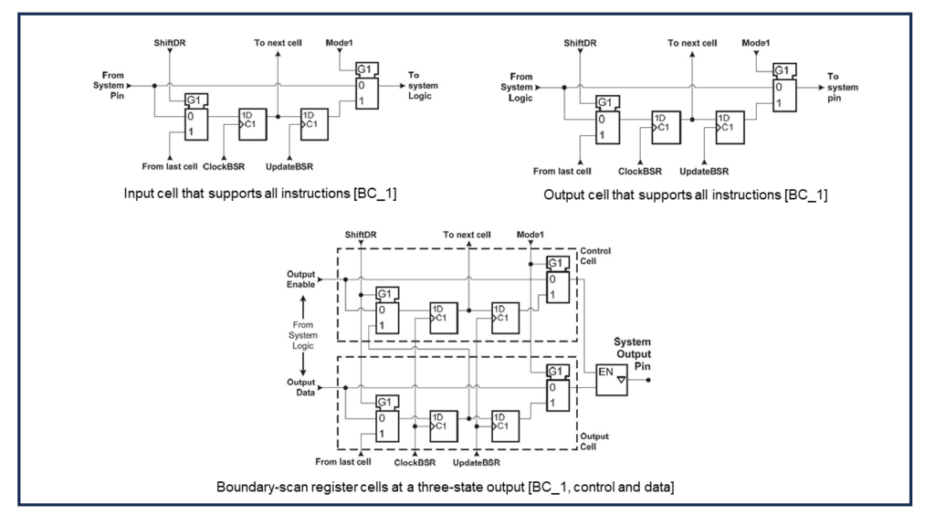
BC_1 – Boundary Scan cell that can be used as an input cell, output cell, control cell, and internal cell. Supports all IEEE 1149.1 instructions.
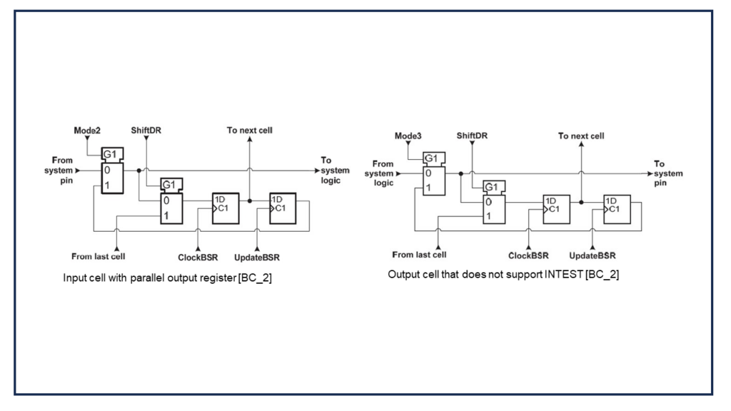
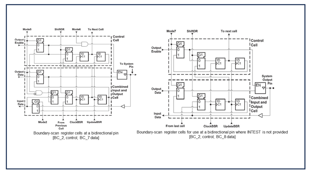
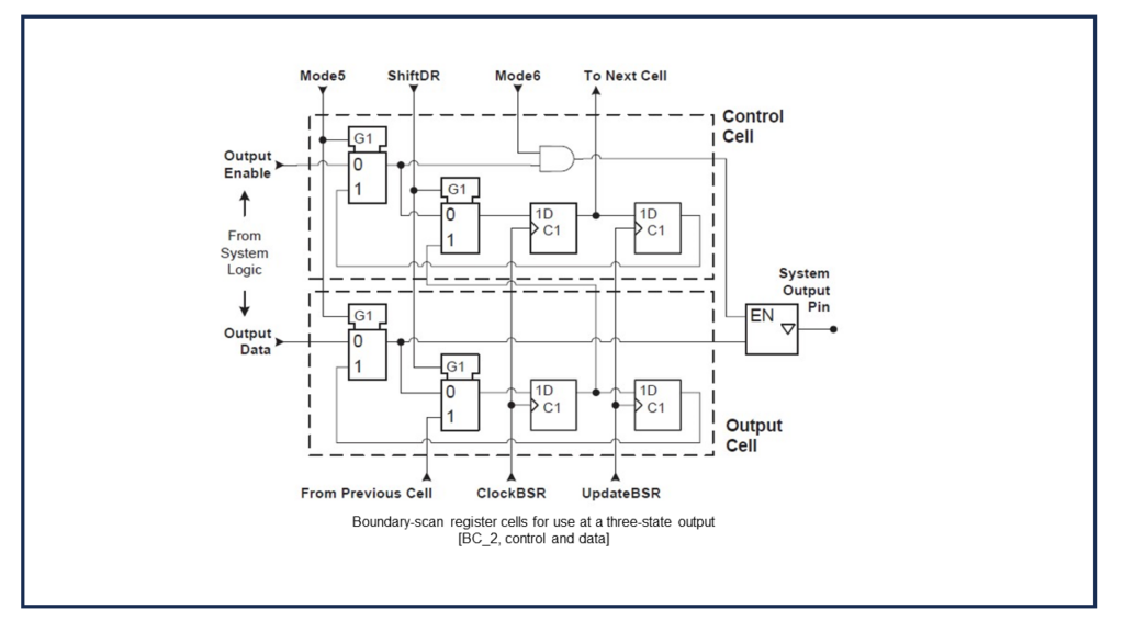
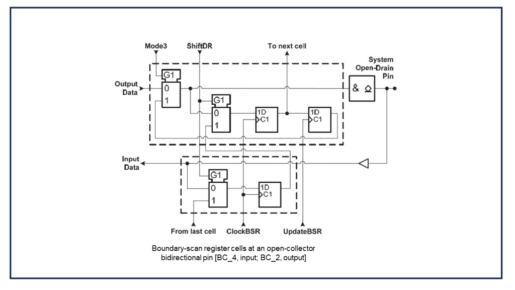
BC_2 – Boundary Scan cell that can be used as an input cell, output cell, control cell, or internal cell similar to BC_1. Cell architecture is like BC_1 with the exception of a multiplexer in the signal patch at the entrance to the cell from the Parallel input.
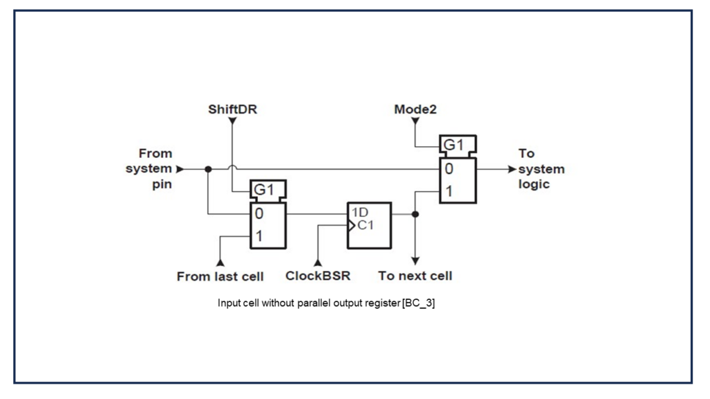
BC_3 – Cell only used for inputs or internal cells as it does not possess an Update latch, but it does support the INTEST instruction.
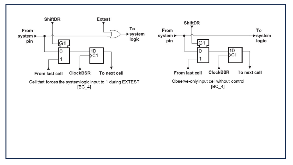
BC_4 – Like the BC_3, this cell does not possess an Update latch. Also, a multiplexer has been removed from the system signal path. Removing the multiplexer removes some potential signal delay through the cell. This cell cannot be used on any input pin except a system clock.
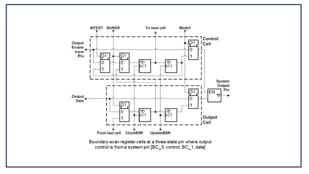
BC_5 – Cell can be used as a merged cell application. Merged cells act as an input cell, thus satisfying the requirement that an input pin have a cell and it can also serve to drive the enable of an output driver.
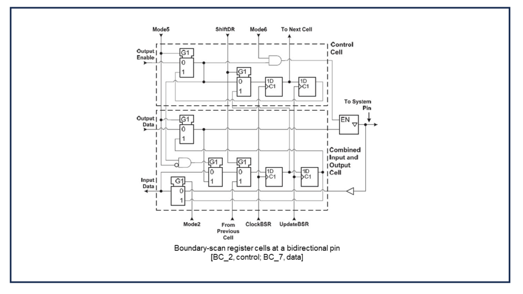
BC_7 – Cell can provide data to the output driver and also monitor pin activity even when the output drive is driving the pin. This is an important feature that was lacking in BC_6. Use of this cell is suggested in lieu of BC_6.
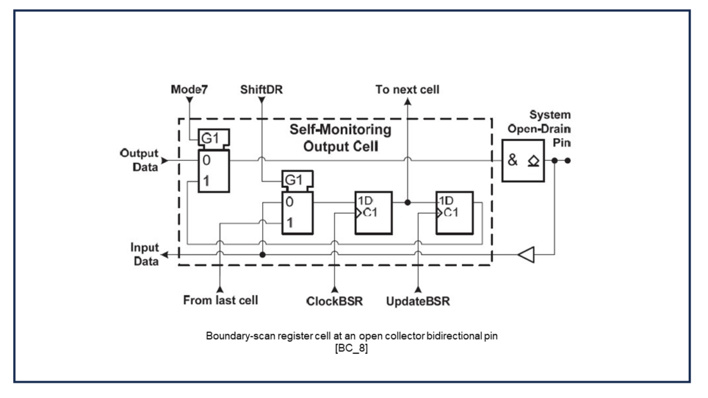
BC_8 – Cell monitors only the pin driver output and therefore does not support the INTEST instruction.
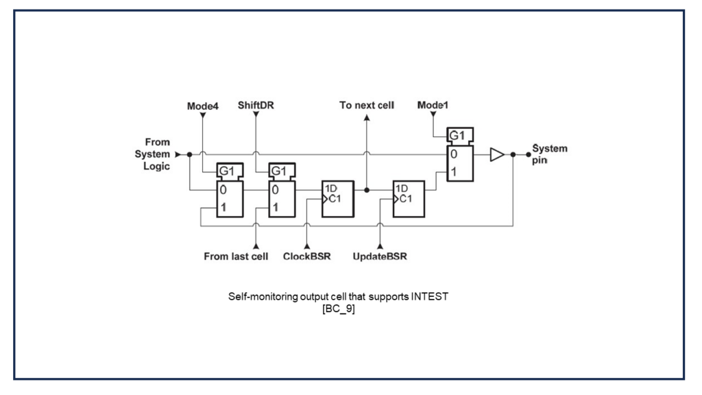
BC_9 – A self-monitoring cell for outputs that does support the INTEST instruction.
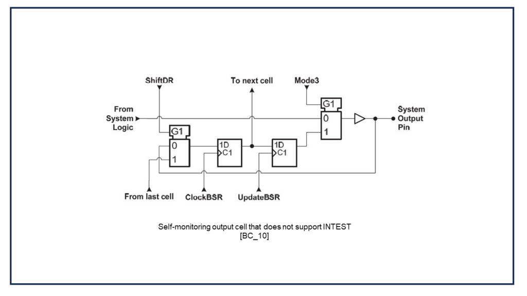
BC_10 – A self-monitoring cell that does not support the INTEST instruction.
There’s more to learn about BSDL, Boundary Scan cells, and the instructions on which they operate than I can cover in a blog post.
Before we can test the interconnects on a PCB, we must validate the BSDLs associated with the Boundary Scan devices on our PCB. Validating the BSDL ensures the various registers, (IDCODE, Instruction, Boundary Scan Register, etc.) are operational and are reporting the expected results. We’ll discuss expected and detected results in a future blog.
Validating the BSDL and Boundary Scan devices is completed with a ScanWorks action known as Scan Path Verify. In the next blog, we’ll learn how ScanWorks validates BSDL files, the device Boundary Scan implementation, and operation of the TAP with a Scan Path Verify action.