
Since its inception, ScanWorks has provided board-level shorts and opens testing of interconnects between Boundary-Scan devices through use of its Automatic Test Pattern Generation (ATPG) feature. ScanWorks ATPG creates the patterns necessary for shorts and opens testing based on the board topology (i.e. connections between devices) and the Boundary-Scan Cell types on the I/O pins within each device. With recent enhancements, ScanWorks can now generate patterns that can be applied by chip-level automatic test equipment (ATE) to test for shorts and opens in the interconnections between silicon “chiplets” in multi-die devices.
A multi-die device, sometimes referred to as a Multi-Chip Module (MCM), is a package configuration containing multiple silicon die or chiplets (Figure 1). Packaging multiple chiplets in a single package has several advantages over monolithic chip designs such as improved performance, lower power consumption, and lower cost.
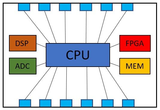
Figure 1. Multi-die Device or MCM
Shorts and opens testing is performed by the manufacturer’s chip-level ATE through the implementation of a test language known as IEEE Standard 1450 – Standard Test Interface Language (STIL) for Digital Test Vector Data. STIL (pronounced “style”) provides an interface between digital test generation tools and test equipment. Most often, STIL vectors are manually created by the chip manufacturer or by a third-party tool. Now ScanWorks has the capability to produce test vectors in the STIL format.
Using ScanWorks, a collection of chiplets is described as a single boundary-scan chain, as you would with any typical ScanWorks project and design. Then a netlist of the die-to-die connections is introduced for an MCM against which to generate the test patterns. The test patterns created by ScanWorks are post-processed to STIL to include pattern, format, and timing information (Figure 2). The file so produced can then be ported to the chip-level ATE – no ScanWorks hardware is necessary for generating or applying the STIL patterns to the MCM.
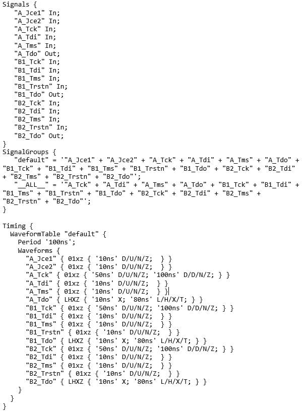
Figure 2. Signal Groups and Timing Waveforms in STIL Format for a 3-die MCM, as produced by ScanWorks
The ScanWorks STIL Option provides chip manufacturers with a simple turnkey automated MCM test authoring solution. The option to produce STIL vectors is selectable from the ScanWorks Interconnect User Interface (Figure 3).
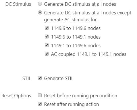
Figure 3. ScanWorks Interconnect User Interface with STIL Option
As a basis for on-board testing, MCM suppliers can provide the ScanWorks project used to generate the STIL patterns for ATE testing to board designers and contract manufacturers who are incorporating the MCM into their end products. With the STIL Option enhancement, ScanWorks now provides a complete end-to-end MCM test and validation solution.