In Episode 2 of the Basys Chronicles, I configured (programmed) the Artix-7 FPGA with a simple Binary-to-Decimal calculator application, through the USB-JTAG port. But, power down the Basys 3, and it goes back to the Built-In Self Test that comes with the board. This week, I flashed the calculator configuration into the nonvolatile SPI flash, making it the default boot-up configuration.
I did try last week at least to flash the SPI with the calculator app, but it failed with no error messages. I figured out subsequently that the board had a Macronix flash, as opposed to the Spansion flash as described in the Digilent YouTube video, Getting started with Vivado and Basys3. It’s probably worthwhile retracing my steps in flashing the Quad SPI.
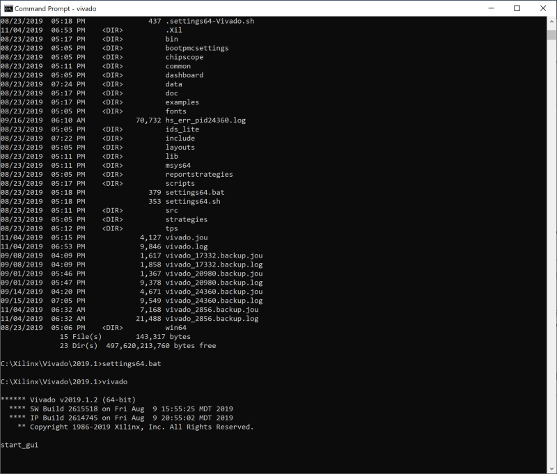
I’m running with the no-charge Vivado HLx WebPACK edition, release 2019.1. I haven’t upgraded to the latest release yet (yes, I will get to it eventually), and for some reason the Vivado environment has to be set up and then executed via the Command line. It took me a while to find this described in AR# 47821 Vivado – How do I source or setup the Vivado environment? I navigated to C:\Xilinx\Vivado\2019.1, and then typed in “settings64.bat”, and then “vivado”:
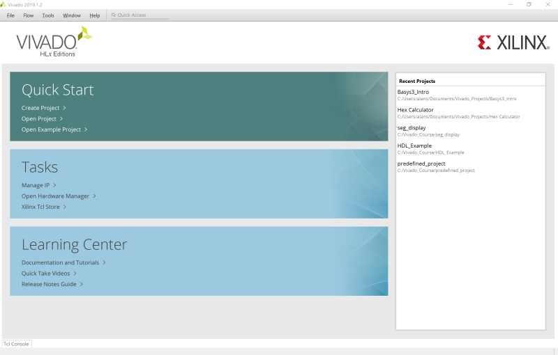
At that time, the Vivado welcome screen appears:
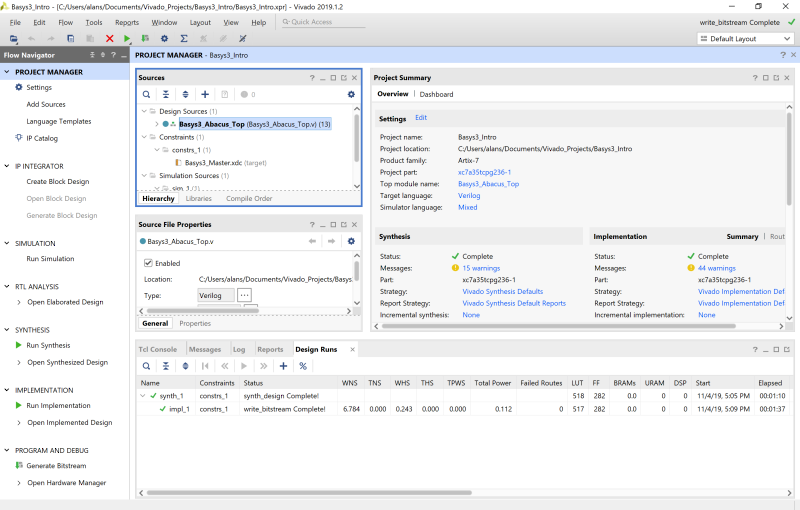
I’ve already created the Basys3_Intro, so I just click on this to open my project:
One thing I didn’t mention last time: you’re going to need to download the source and constraint files either from Digilent’s website itself at https://reference.digilentinc.com/learn/programmable-logic/tutorials/basys-3-abacus/start or via GitHub at https://github.com/Digilent/Basys-3-Abacus. Note: I found the GitHub easier to navigate than the Digilent site: the tutorials are on the Diligent website, but they are harder to find. At least in the GitHub, there are several projects easily seen:
Abacus: our binary-to-decimal calculator
GPIO: the system BIST that rotates the seven-segment display 0000 -> 9999
Keyboard: Displays keyboard characters via an application on the USB-UART bridge
XADC_Demo: The seven-segment display shows current voltage applied across the selected XADC pins.
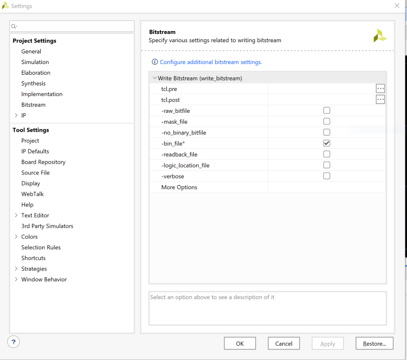
So, back to the Abacus (binary to decimal calculator) project: everything is as it was in Episode 1; I just need to build the .bin file targeted to the Macronix flash. The first step is to go to Tools -> Settings -> Bitstream, and ensure that the .bin file (in addition to the .bit file) will be generated:
Then, Run Synthesis, and then Open Synthesized Design. From the Tools Menu, Edit Device Properties, set Enable Bitstream Compression to True, set Configuration Rate to 33MHz, set the Configuration Mode to Quad SPI, then Close and Save the synthesized design window.
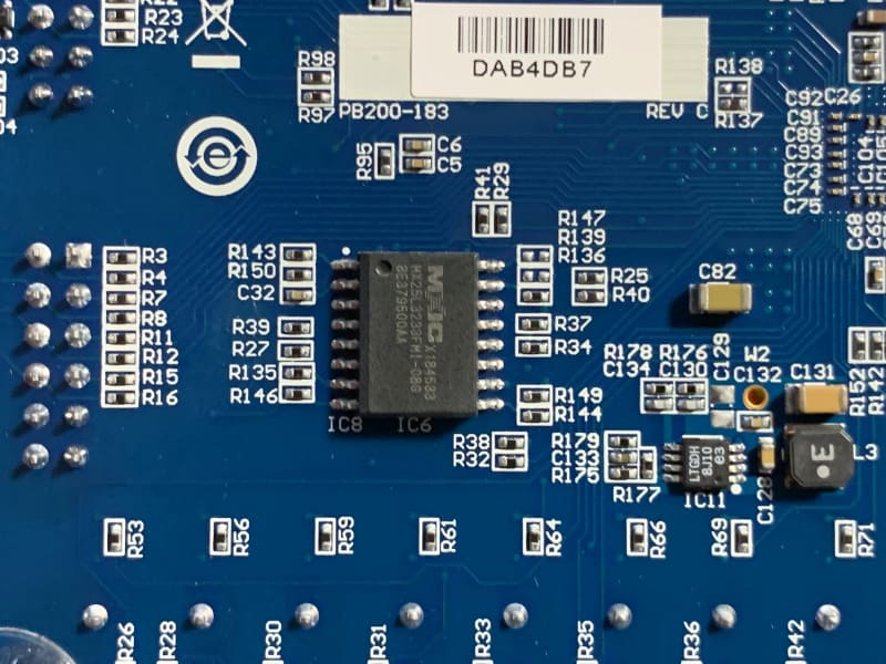
Before programming the flash, we first need to select the Macronix part. It’s on the bottom of the board, and here’s a magnified picture of it:
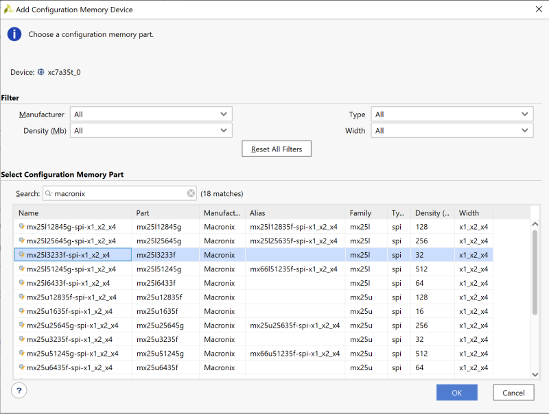
We see that it’s an MX25L3233F part, so we need to select that in the Add Configuration Memory Device screen:
Click OK, and that programs the flash successfully. Now, when I power down and power up the board, the BIST routine has been replaced by the calculator routine! Pretty cool.
Next episode, I’ll build a new project from scratch using the BIST routine (also called GPIO within the Digilent GitHub projects), and re-flash it back to the default.


