We know that the board bring-up process can be extremely challenging on today’s complex, high-speed designs. How do we get the iterative validation, test and debug steps off of the critical path of new product introduction?
We’ve previously defined “board bring-up” as a phased process whereby an electronics system, inclusive of assembly, hardware, firmware, and software elements, is successively tested, validated and debugged, iteratively, in order to achieve readiness for manufacture.
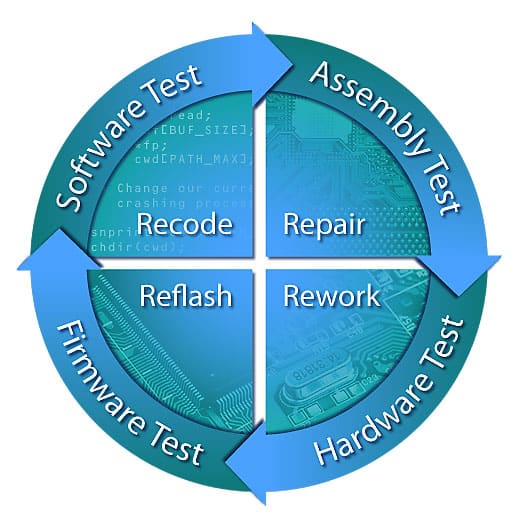
Any time a new prototype run is done as part of a new product introduction cycle, a repeatable set of steps are needed to ensure that the design is working as per specifications. Firstly, it must be verified that the board has been assembled correctly. Next, basic hardware test is needed (to ensure that the individual devices and buses/interconnects are operational – which involves testing power, clocks, and basic functional connectivity). After that, any firmware and low-level software must be debugged, to get the board operational; so that the next phase of testing may be applied, such as memory test or signal integrity validation. Finally, a system’s operating system is loaded, and any embedded software is checked. This sequence is represented visually here:

We cover the fundamentals of assembly test and hardware test in much of our collateral, most recently in Detection and Diagnosis of Printed Circuit Board Defects and Variances. On today’s designs, it’s essential to verify the structural, functional and performance attributes of a design using such tools as boundary-scan test, processor-controlled test and Intel HSIO, respectively. For example, a structural defect (such as a stuck-at fault) on one net of a PCI Express lane will affect the performance of the entire bus and yet may escape conventional functional test. Such a defect would be detected by boundary scan. Alternatively, Intel HSIO would show the reduced margin on that lane, thereby preventing a faulty system from being shipped.
Things get even more interesting when it comes to firmware and software test. The SourcePoint debugger is exceptional when it comes to debugging these most challenging problems. Imagine an issue where an Ethernet port is working only intermittently. First it’s necessary to rule out hardware structural, functional and performance issues, using boundary-scan test, processor-controlled test, and Intel HSIO. Then, the real debugging can begin in earnest. It may be that the device’s driver isn’t handling interrupts properly. In this case, the trace capabilities of SourcePoint can be used to provide a comprehensive picture of the system’s behavior, confirming timing assumptions and identifying any anomalies in the chip’s behavior. For example, the exact number of instructions in an ISR routine can be measured, as well as the interval between the transmission of a data packet and when the transmit-complete interrupt is received. Then, the interrupt behavior and patterns of the system in a variety of situations can be traced, such as with simultaneous USB and Ethernet activity.
Collectively, the boundary-scan test, processor-controlled test, Intel HSIO and SourcePoint debugger constitute a tremendous toolkit for board bring-up.


