
Because ASSET is a pioneer in the use of non-intrusive solutions for validation, test and debug (using what we call “embedded instrumentation”), we often get asked if legacy testers like In-Circuit Test (ICT) machines can be used for the testing of high-speed I/O. Testing of such buses on ICT has become problematic over the years because of the limited access issue, but there are a number of alternative technologies that do run on ICT that can in a limited way test such buses. I’d like to briefly examine three such technologies – IEEE 1149.6, bead probes, and the emerging IEEE P1149.8.1 – and comment on their use cases…
IEEE 1149.6
IEEE 1149.6 (aka “AC-JTAG”, or more colloquially, “dot6”) is an extension of the IEEE 1149.1 boundary scan standard which addresses testing of AC-coupled or differential buses. Standardized in 2004, dot6 overcomes the static DC nature of 1149.1 testing to provide shorts and opens test coverage on these advanced digital nets. When combined with a comprehensive 1149.1 interconnect test, dot6 can support test coverage on high-speed nets regardless of the operating speed.
Since many modern ICT machines support boundary scan, they may also support dot6. The best approach is to ask your vendor. One thing to be sure to inquire about is whether the ICT AC-JTAG solution supports the testing of 1149.6 to 1149.6 nets, 1149.6 to 1149.1, 1149.1 to 1149.6, and AC-coupled 1149.1 to 1149.1. You want to be sure that all of the specification scenarios are provided for, especially to get the highest level of shorts coverage on these types of nets.
The disadvantage of using dot6 solely on ICT is, of course, that it can only be used on the ICT. Benchtop 1149.6 solutions provide more flexibility in terms of doing dot6 testing for the lifecycle of the product, particularly at prototype and at repair/return depots.
Another disadvantage of dot6 is that, even though it has been standardized for about six years now, it is nowhere near ubiquitous on merchant silicon. This is changing, but slowly. If you’re not sure about whether a chip on your upcoming design is going to support dot6 as part of your test strategy, contact us – we’re familiar with the current status of many devices.
If dot6 can’t be used on a given bus (if, for example, the silicon doesn’t support it), alternative embedded instrumentation technologies such as processor-controlled test or bit pattern generation/checking will be needed.
Bead Probes
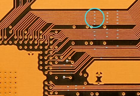
Bead probes are alternatives to regular 35-mil test pads which are connected to traces with stubs. Bead probes are made from tiny “beads” of solder which are placed directly upon the trace. Ideally they are of the same width of the trace (say 5 mils) and are maybe 15-20 mils long. The blue circle in the image below indicates some of the bead probes placed on high-speed signal traces in this PCB design
Being much smaller than regular test pads, they ideally do not affect the characteristics of the transmission line and therefore do not change the signal integrity of the bus. They also minimize the use of the expensive 39 mil and 50 mil test probes, therefore dropping fixture costs. A good reference for this technology is at www.agilent.com/see/beadprobe.
One disadvantage of bead probes is that the technology is licensed by Agilent Technologies and other ICT vendors must be licensed to use this technology. And, of course, if a high-speed net does not come to the surface of a PCB, bead probes cannot be used.
IEEE P1149.8.1
Also known as “Selective Toggle”, this emerging IEEE standard is intended to address some of the limitations of today’s ICT “powered opens” technology. The powered opens test method uses boundary scan as a stimulus (as opposed to test probes, where test access is a problem) and uses capacitive sensing plates to provide test coverage, particularly on passive components and vacant connectors. It’s a very powerful and popular solution because it obviates the need for populating processors, chipsets, memory, and other costly components at the ICT structural test stage.
Some of the “powered opens” shortcomings that the new IEEE standard is intended to address are:
- Inadequate shorts coverage: “powered opens” is in fact an opens testing methodology.
- Canceling effect on differential circuits: so cannot be used to test AC and differential nets.
- Long boundary scan chains render the toggle frequency too low for diagnostic granularity using the time-domain approach to powered opens.
The challenge that IEEE P1149.8.1 faces is shared by all new standards: it needs to be adopted within silicon before it can be useful. And it can be a challenge to convince the silicon makers to add this logic into their devices. IEEE 1149.1 took the good part of a decade to become ubiquitous within chips, and up to now IEEE 1149.6 appears to be following roughly the same trajectory. I would expect that 1149.8.1 will also have a long-term adoption cycle.